Home > Products > 8-inch diameter 200mm tire width 45 unilateral finale cyclone model
8-inch-diameter-200mm-tire-width-45-unilateral-finale-cyclone-model-13.jpg
8-inch-diameter-200mm-tire-width-45-unilateral-finale-cyclone-model-1.png
8-inch-diameter-200mm-tire-width-45-unilateral-finale-cyclone-model-10.png
8-inch-diameter-200mm-tire-width-45-unilateral-finale-cyclone-model-12.jpg
8-inch-diameter-200mm-tire-width-45-unilateral-finale-cyclone-model-3.png
8-inch-diameter-200mm-tire-width-45-unilateral-finale-cyclone-model-4.png
8-inch-diameter-200mm-tire-width-45-unilateral-finale-cyclone-model-7.jpg
8-inch-diameter-200mm-tire-width-45-unilateral-finale-cyclone-model-8.png
8-inch-diameter-200mm-tire-width-45-unilateral-finale-cyclone-model-9.png
img

retail price:
$ 53.57
wholesale price:
To be discussed
Customized price:
To be discussed
Custom made:
Tire
Fixed axis method
Wirewound resistor
Connectors
Wheels

Recommended Products

Product Introduction

8-inch long-axis motor "Cyclone Model": Exclusively adapted for 200mm diameter × 45mm tire width, no secondary processing required; the single-sided pressure shaft structure enhances stability while taking into account "cyclone-level" power output, suitable for small electric mobility, leisure equipment and other scenarios. Bulk purchases support customization, and installation is convenient and saves time!
Product Introduction

Installation Instructions

1. Connect the motor to the controller and power supply according to the wiring diagram on the controller.

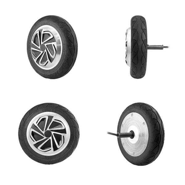
2.The tire is installed outside the outer rotor hub.

3. When the power cord passes through metal parts, it should be protected by non-metallic products.

4. When the driver is powered on, pay special attention to whether the motor stops rotating, gets stuck, or heats up abnormally quickly.

The power must be turned off and on within three seconds to adjust the electrical angle or drive output to prevent motor failure

Installation Instructions
1. Connect the motor to the controller and power supply according to the wiring diagram on the controller.
2. The tire is installed outside the outer rotor hub.
3. When the power cord passes through metal parts, it should be protected by non-metal products.
4. Special attention: When the motor is powered on by the driver and the motor does not move or freezes, or it heats up abnormally quickly, the power must be turned off and on within three seconds to adjust the electrical angle or drive output to avoid motor failure

Product Parameters

The main parameters

Number Projects Specification Remarks
1 Motor diameter 200mm (slight deviation including tire size) Subject to actual product
2 Rated voltage 48V
3 Rated power 350W
4 Rated rotating speed 500±50rpm
5 Rated current 8±0.5A
6 Theoretical torque 15.9N/M
7 Degree of phases 120°
8 Number of poles 15 pole pairs 30PCS
9 Out of the shaft Single-sided D-shaped pressing shaft
10 Lead exposed 300mm
11 Size of connectors 3+6 waterproof connector
12 Brake mode Electromagnetic brake
13 Shaft material 45cr (alloy steel)
14 Waterproof rating IP55
15 Maximum load 120kg
16 Environmental requirements -20℃ to 65℃
Close
?