Home > Products > 4-inch diameter 105mm tire width 42 opening 62 double-sided threaded shaft PU water guide groove
4-inch-diameter-105mm-tire-width-42-open-62-bilateral-threaded-shaft-PU-water-guide-tank-model-6.png
4-inch-diameter-105mm-tire-width-42-open-62-bilateral-threaded-shaft-PU-water-guide-tank-model-1.jpg
4-inch-diameter-105mm-tire-width-42-open-62-bilateral-threaded-shaft-PU-water-guide-tank-model-2.jpg
4-inch-diameter-105mm-tire-width-42-open-62-bilateral-threaded-shaft-PU-water-guide-tank-model-3.jpg
4-inch-diameter-105mm-tire-width-42-open-62-bilateral-threaded-shaft-PU-water-guide-tank-model-4.jpg
4-inch-diameter-105mm-tire-width-42-open-62-bilateral-threaded-shaft-PU-water-guide-tank-model-6.jpg

retail price:
$
Wholesale Price:
To be discussed
Customized price:
To be discussed
Custom made:
Tire
Fixed axis method
Wirewound resistor
Connectors
Wheels

Recommended Products

Product Introduction

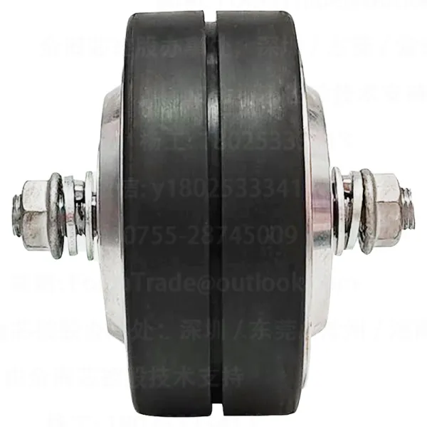
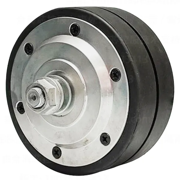
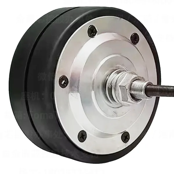
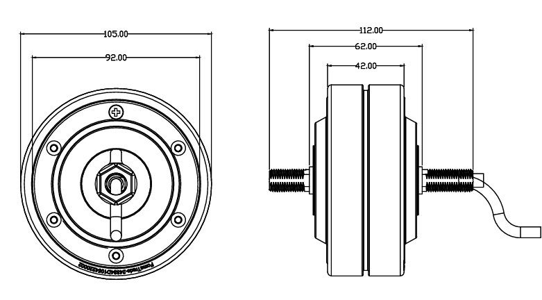
4-inch motor specifically designed for smart luggage: 105mm diameter x 42mm width, custom-made to perfectly match luggage wheel specifications; PU tread with water guide grooves for enhanced anti-slip performance and durability in wet conditions; 62mm gear opening + double-sided threaded shaft, supporting standardized assembly, eliminating the need for secondary processing and ensuring efficient installation; suitable for smart towing and automatic following luggage
Product Introduction

Product Parameters

The main parameters

Number Projects Specification Remarks
1 Motor diameter 105mm (slight deviation including tire size) Subject to actual product
2 Rated voltage 24V
3 Rated power 250W
4 Rated rotating speed 1800±50rpm
5 Rated current 6±0.5A
6 Theoretical torque 4.8 N/M
7 Degree of phases 120°
8 Number of poles 20 poles
9 Out of the shaft Double-sided threaded shaft (mm)
10 Lead exposed 500mm
11 Size of connectors 3+6 waterproof connector
12 Brake mode Electromagnetic brake
13 Shaft material 45cr (alloy steel)
14 Waterproof rating IP55
15 Maximum load 100kg
16 Environmental requirements -20℃ to 65℃

Close
Installation Instructions
1. Connect the motor to the controller and power supply according to the wiring diagram on the controller.
2. The tire is installed outside the outer rotor hub.
3. When the power cord passes through metal parts, it should be protected by non-metal products.
4. Special attention: When the motor is powered on by the driver and the motor does not move or freezes, or it heats up abnormally quickly, the power must be turned off and on within three seconds to adjust the electrical angle or drive output to avoid motor failure