


| Number | Projects | Specification | Remarks |
|---|---|---|---|
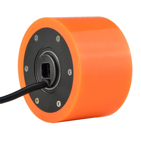
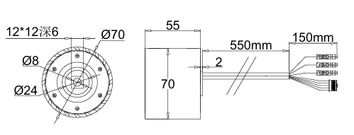
| 1 | Motor diameter | 70mm (slight deviation including tire size) | Subject to actual product |
| 2 | Rated voltage | 24V | |
| 3 | Rated power | 150W | |
| 4 | Rated rotating speed | 1600±50rpm | |
| 5 | Rated current | 5±0.5A | |
| 6 | Theoretical torque | 2.9N/M | |
| 7 | Degree of phases | 60° | |
| 8 | Number of poles | 7 pole pairs | 14PCS |
| 9 | Out of the shaft | Central hole 8mm | |
| 10 | Lead exposed | 300mm | |
| 11 | Size of connectors | Bullet connector + XH terminal 2.0 connector | |
| 12 | Brake mode | Electromagnetic brake | |
| 13 | Shaft material | 45# steel (quenched and tempered) | |
| 14 | Waterproof rating | IP55 | |
| 15 | Maximum load | 50kg | |
| 16 | Environmental requirements | -20℃ to 65℃ |


