Home > News > WINAMICS 8-Inch 200mm Unilateral Axle Hub Motor Maintenance & Troubleshooting

Maintenance and Troubleshooting Guide for the WINAMICS 8-Inch Unilateral Axle Hub Motor

2026-10-10
WINAMICS maintenance and troubleshooting guidance for the 8-inch, 200mm diameter and 84mm tire-width unilateral axle hub motor, covering inspections, electrical checks, common faults, safety limits and support boundaries.

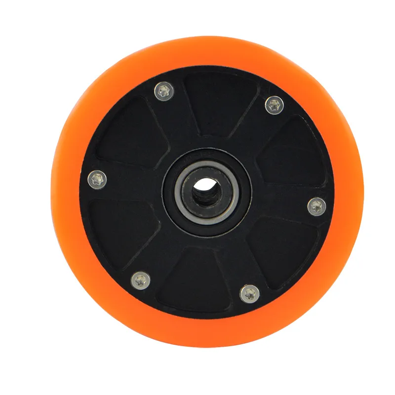
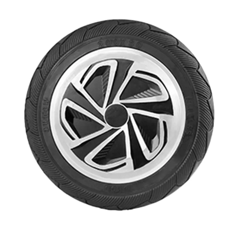
The WINAMICS 8-inch unilateral axle hub motor has a 200 mm motor diameter and an 84 mm tire width. It is designed for compact equipment such as small go-karts and recreational equipment. This maintenance and troubleshooting guide provides a practical reference for maintenance engineers, technical support teams and equipment users.

The guide covers routine inspection, electrical connection checks, common operating faults, safe inspection limits and support boundaries. Always follow the equipment manufacturer's procedures, applicable electrical safety regulations and the relevant motor-controller documentation.

Product Reference

Brand WINAMICS
Motor type Unilateral axle hub motor
Nominal dimensions 200 mm diameter × 84 mm tire width
Typical application context Small go-karts, recreational equipment and other compatible compact equipment

Before Any Inspection

Stop the equipment

Park the equipment securely, remove the load where appropriate and prevent unintended movement or startup.

Isolate the power

Switch off the system and isolate the battery or other power source according to the equipment procedure. Allow stored energy to discharge safely.

Use suitable tools

Use appropriate insulated electrical test tools and mechanical tools. Measurements should be performed only by qualified personnel.

Important: Do not open, modify or re-machine the hub motor unless this has been specifically authorized by the manufacturer. Do not bypass controller protections or continue operation when a safety-critical fault is suspected.

Preventive Maintenance Checklist

  1. Inspect the exterior: Check the motor housing, unilateral axle area, wheel or tire interface and visible fasteners for impact damage, looseness, deformation or abnormal wear.
  2. Check the mounting: Confirm that the motor is installed securely and that there is no unusual movement, interference or contact with adjacent components.
  3. Inspect cables and connectors: Look for loose connections, damaged insulation, exposed conductors, contamination, moisture ingress or signs of overheating.
  4. Check operating noise and vibration: Compare the current operating condition with normal equipment behavior. Abnormal noise, vibration or irregular rotation should be investigated before continued use.
  5. Review the controller and battery system: Confirm that the controller, energy battery pack and motor are correctly matched and that no warning, protection or fault indication is present.
  6. Keep records: Record inspection dates, observed symptoms, fault codes, environmental conditions and corrective actions to support accurate diagnosis.

Electrical Connection Checks

Electrical checks should begin with a visual inspection and system documentation review. Confirm the wiring arrangement, connector identification and controller configuration before applying test equipment.

  • Verify that the motor power connections and signal connections are fully seated and correctly identified.
  • Check for reversed, loose, corroded or damaged terminals.
  • Inspect cable routing for crushing, sharp bends, abrasion and contact with hot or moving parts.
  • Compare measured values with the approved specifications for the complete low-voltage three-electric system, motor controller and energy battery pack.
  • Do not use an isolated measurement result to approve the motor if the controller, battery, wiring or mechanical installation may also be contributing to the fault.

Common Symptoms and Initial Troubleshooting

Symptom Initial checks Recommended boundary
Motor does not start Check power isolation status, battery availability, controller indications, connectors and any emergency-stop or interlock condition. If the system remains inactive after basic connection checks, stop repeated restart attempts and arrange qualified diagnosis.
Insufficient power or slow response Check battery condition, controller settings, load, mechanical resistance, tire or wheel installation and cable connections. Do not increase current or alter controller parameters without confirming compatibility and receiving technical approval.
Overheating or abnormal current Stop operation. Inspect for overload, mechanical obstruction, incorrect wiring, poor connections, controller issues and restricted heat dissipation. Do not continue operation until the cause has been identified. Never treat overheating as a condition to be solved only by resetting the system.
Irregular operation, noise or vibration Inspect mounting, axle alignment, wheel or tire contact, cable interference and signs of mechanical damage. Remove the motor from service if the condition is worsening or affects vehicle or equipment control.
Intermittent fault Check connectors, harness movement, moisture, vibration-related looseness, controller records and operating conditions when the fault occurs. Document the symptoms rather than repeatedly cycling power, as intermittent faults may cause secondary damage.

When to Stop Using the Motor

Immediately stop use and isolate the system when any of the following conditions is observed:

  • Visible cracking, deformation, severe impact damage or loose structural components;
  • Burning odor, smoke, melted insulation or clear evidence of electrical overheating;
  • Repeated abnormal current, overheating, startup failure or controller protection;
  • Severe vibration, grinding noise, wheel interference or loss of normal control;
  • Any condition that cannot be assessed safely by the available maintenance personnel.

Information to Prepare for Technical Support

When contacting Shenzhen Jinhaixin Holdings Co., Ltd. or the WINAMICS support team, provide as much of the following information as is available:

  • Motor model or product identification information;
  • Equipment type and operating application;
  • A clear description of the symptom and when it occurs;
  • Controller or system fault codes, if available;
  • Relevant inspection findings, photographs and wiring information;
  • Any recent changes to installation, load, controller settings or operating environment.
Reliable maintenance starts with correct system-level diagnosis. The WINAMICS unilateral axle hub motor is part of a low-voltage three-electric system that may include a drive controller, energy battery pack, wiring and mechanical components. Checking these elements together helps reduce misdiagnosis and avoid secondary damage. For conditions beyond routine inspection or documented equipment procedures, consult qualified technicians or contact Shenzhen Jinhaixin Holdings Co., Ltd. for appropriate technical support.
Name *
Email *
Message *
Recommended Products
8-inch diameter, 200mm tire width, 45mm single-sided pressure shaft cyclone motor
优势特点:1. "Stable Cyclone Power Output": Equipped with a single-sided pressure shaft structure, it enhances operational stability from the root and reduces vibration and component wear during high-frequency use; at the same time, it is tuned to deliver "cyclone-level" strong power, with fast start-up response and linear power output, which not only meets the smooth range requirements of commuter devices, but also adapts to the short-term high-frequency power scenarios of leisure devices. 2. "More Flexible Batch Customization": Supports large-scale batch procurement and parameter customization. Power parameters and shaft length details can be adjusted according to equipment model and usage scenario. Provides standardized B-end procurement services, with dedicated personnel handling the entire process from sample testing to batch delivery, balancing customization flexibility and delivery efficiency. It is the preferred supply chain solution for transportation equipment manufacturers and leisure equipment brands. Installation Instructions 1. Connect the motor to the controller and power supply according to the wiring diagram on the controller. 2.The tire is installed outside the outer rotor hub. 3. When the power cord passes through metal parts, it should be protected by non-metallic products. 4. When the driver is powered on, pay special attention to whether the motor stops rotating, gets stuck, or heats up abnormally quickly. The power must be turned off and on within three seconds to adjust the electrical angle or drive output to prevent motor failure