
In electric go-karts, “power transmission efficiency” is not only a motor spec—it’s the combined result of magnetic design, mechanical stiffness, alignment accuracy, and heat stability under repeated launches. Among these variables, the single-side press-fit shaft (single-side press axle) structure in an 8-inch outrunner hub motor is gaining attention because it addresses a common bottleneck: micro-misalignment and vibration that silently consume torque, increase noise, and accelerate bearing wear.
This article explains the technical logic in a neutral, engineering-first way—so both design engineers and sourcing decision-makers can evaluate whether this structure is the right fit for a low-speed, high-torque motor go-kart drivetrain.
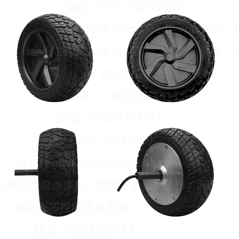
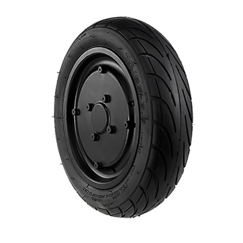
For small electric go-karts, the practical target is often fast launch response and stable torque in the 0–25 km/h range. In this speed band, an outrunner hub motor naturally aligns with the physics of torque production: torque is proportional to the radius at which electromagnetic force acts. By placing the rotor outside (larger effective radius), an outrunner can achieve higher torque at lower RPM compared with many inrunner layouts of similar stack length.
A simplified viewpoint: the stator creates a rotating magnetic field, the rotor magnets follow, and torque emerges from the interaction across the air gap. For small kart hub motors, maintaining a consistent air gap is critical because local variations lead to: cogging feel, torque ripple, and additional iron/copper losses that show up as heat.
While exact slot/pole combinations vary by supplier, most kart-focused hub motors aim to reduce low-speed ripple through optimized winding distribution and magnet arc design. In real-world go-kart duty (frequent start-stop, throttle modulation), a smoother electromagnetic torque curve reduces chassis vibration and makes throttle control more predictable—both are “efficiency” gains from the rider’s perspective.
Reference note (engineering consensus): Industry guidance for rotating machines consistently links air-gap stability and mechanical runout to torque ripple, acoustic noise, and bearing fatigue life—especially under repetitive shock loads such as kart launches and curb strikes.
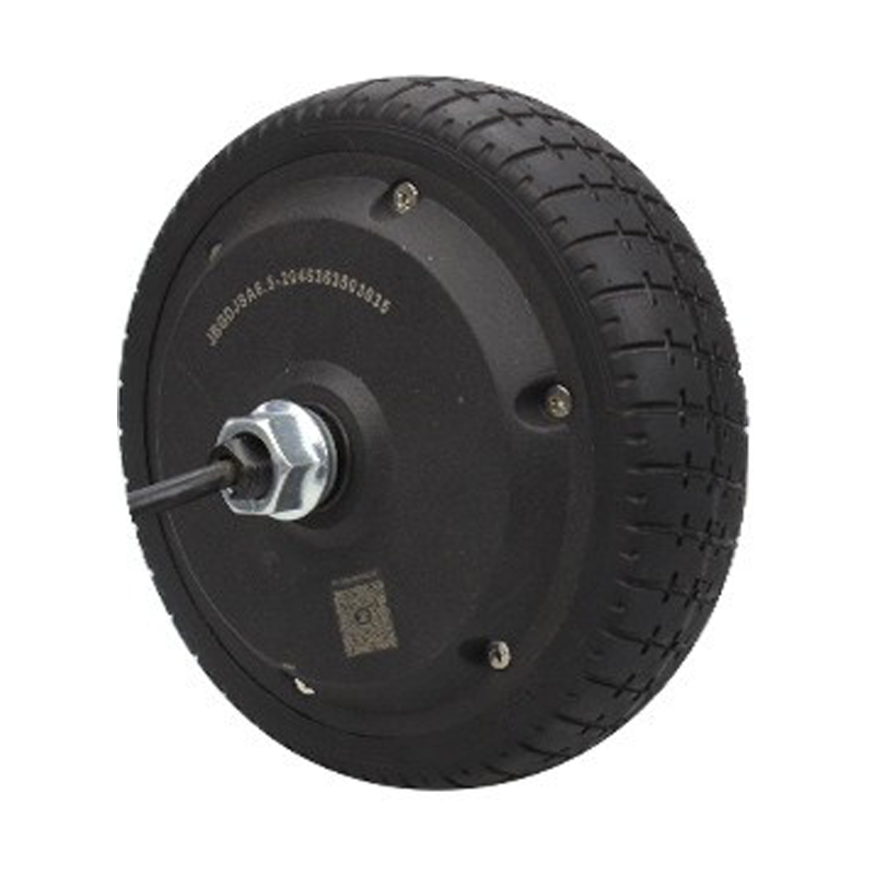
Traditional designs often rely on dual-side support concepts to “hold everything straight.” In practice, however, more support points can introduce more tolerance stack-up, more assembly complexity, and more chances to preload bearings incorrectly. A single-side press-fit shaft structure focuses on a tighter, cleaner reference system—if executed with correct fits and assembly control.
| Aspect | Dual-Side Support (common approach) | Single-Side Press-Fit Shaft (focus structure) |
|---|---|---|
| Alignment chain | More interfaces to align; higher risk of tolerance stack-up | Fewer datum transfers; easier to control runout if fits are correct |
| Vibration & noise | Can be good, but sensitive to assembly preload mismatch | Often improved when rotor concentricity is stable and preload is controlled |
| Bearing life sensitivity | Higher: incorrect preload on either side accelerates fatigue | Lower if press-fit and seating are consistent; fewer chances to “over-constrain” |
| Assembly repeatability | More steps; more torque points to audit | Cleaner process window; easier to standardize torque + runout checks |
In kart duty, repeated shock loads (hard launches, braking, cornering, occasional curb contact) can amplify tiny assembly errors. When the rotor drum experiences micro-wobble, the motor faces a chain reaction: air-gap variation → torque ripple → vibration → additional bearing friction → heat. Even if electrical efficiency looks fine on a datasheet, mechanical instability can pull down real drivetrain efficiency.
A well-executed single-side press-fit shaft typically improves stiffness and repeatability at the critical reference interface, making it easier to keep rotor concentricity stable over time.
Go-karts stress motors in a way that lab benches rarely reproduce: short bursts of high current, limited airflow at low speed, and repeated heat soak. As temperature rises, copper resistance increases, which can reduce effective torque per amp and force the controller to limit current.
A common engineering reference is copper’s temperature coefficient around 0.39%/°C. In simple terms, if winding temperature rises by ~50°C, resistance can increase by roughly ~20%, raising copper loss at the same current.
More stable alignment reduces frictional and vibrational losses that become heat. A rigid, repeatable shaft seat also helps keep bearing loads within intended ranges, lowering “extra” heat during long sessions.
The net effect: structural stability supports magnetic stability, and magnetic stability supports thermal stability—an underrated loop that preserves consistent torque output over a race day or rental fleet shift.
Single-side press-fit designs can deliver strong results, but only if installation quality matches the structure’s intent. The biggest field failures usually come from incorrect bolt strategy, poor concentricity control, or damage during press operations.
Uneven or excessive preload can distort mounting faces and introduce misalignment. For small hub motor assemblies, many teams adopt a simple discipline: use a calibrated torque tool, tighten in a star pattern, and re-check after initial seating. As a practical range reference for M6 class fasteners used in similar assemblies, torque is often around 8–12 N·m depending on grade, lubrication, and joint design—always confirm with your fastener spec and joint engineer.
Eccentricity is one of the fastest ways to lose efficiency and create noise complaints. In practice, teams typically check:
As a realistic engineering target for small rotating assemblies, keeping total runout within 0.05–0.15 mm (depending on wheel size, bearing selection, and speed) is a common starting point for stable, quiet operation. Tighter is better—but only if the manufacturing process can hold it consistently.
A press-fit interface is not forgiving of burrs, contamination, or tilted pressing. Cleanliness, correct tooling, and controlled pressing speed reduce the risk of microscopic galling that later becomes fretting, runout drift, or bearing preload changes.
Because kart builds vary widely (track grip, tire diameter, controller limits, rider weight), outcome data should be interpreted as directional. Still, when teams improve shaft referencing and reduce runout on outrunner hub motors, they often report a similar pattern:
| Observed metric (typical) | Before (looser alignment) | After (controlled press-fit + runout checks) |
|---|---|---|
| Noise / harshness at launch | Noticeable “growl” or vibration | Perceived reduction; smoother throttle take-up |
| Bearing temperature rise | Higher in long sessions | Often lower by ~5–15°C in comparable duty cycles* |
| Maintenance interval | More frequent bearing checks | More stable intervals; fewer “mystery” noise returns |
*Reference range based on common field feedback in small EV drivetrains where alignment and preload control are improved; results depend on ambient temperature, bearing type, sealing, and duty profile.
Procurement takeaway: When suppliers discuss “efficiency,” ask for their runout control method, press-fit tolerance approach, and QC checkpoints (e.g., whether they record radial/axial runout per batch). These process details often predict field stability better than peak power claims.
To evaluate an 8-inch outrunner hub motor with a single-side press-fit shaft for a small go-kart, decision-makers typically request documentation in three layers:
Rated/peak current limits, back-EMF constant, torque constant, efficiency curve at low RPM, controller compatibility.
Shaft fit standard, bearing model and sealing, runout targets, mounting interface tolerances, wheel-side load limits.
Temperature rise test method, winding insulation class, thermal protection strategy, recommended duty cycle for kart use.
For teams building repeatable products (rental fleets, club racing packages, campus projects), these details reduce rework and warranty exposure—often more than any single “headline” torque number.
WWTrade works with engineering and sourcing teams to translate application needs (torque band, duty cycle, mounting constraints, QC targets) into a motor configuration that can be manufactured consistently—then supported with integration guidance and documentation.
Explore WWTrade’s 8-inch outrunner hub motor solutions with single-side press-fit shaft supportTypical discussion topics: runout targets, bearing sealing options, controller matching, and assembly/QC checkpoints for stable fleet performance.


