
Mastering the standard installation and debugging process of 5-inch low-speed motors is crucial for ensuring the long-term stable operation of your equipment. In this guide, we'll walk you through the entire process, from tool preparation to load testing, to help you achieve 'stable installation, accurate operation, and long service life'.
Before you start installing the 5-inch motor, it's essential to prepare the necessary tools. Here's a list of tools you'll need:
Additionally, you must adhere to safety precautions. Always ensure the power supply is disconnected before installation to prevent electrical shocks. Wear protective gear such as gloves and safety glasses to safeguard yourself from potential hazards.
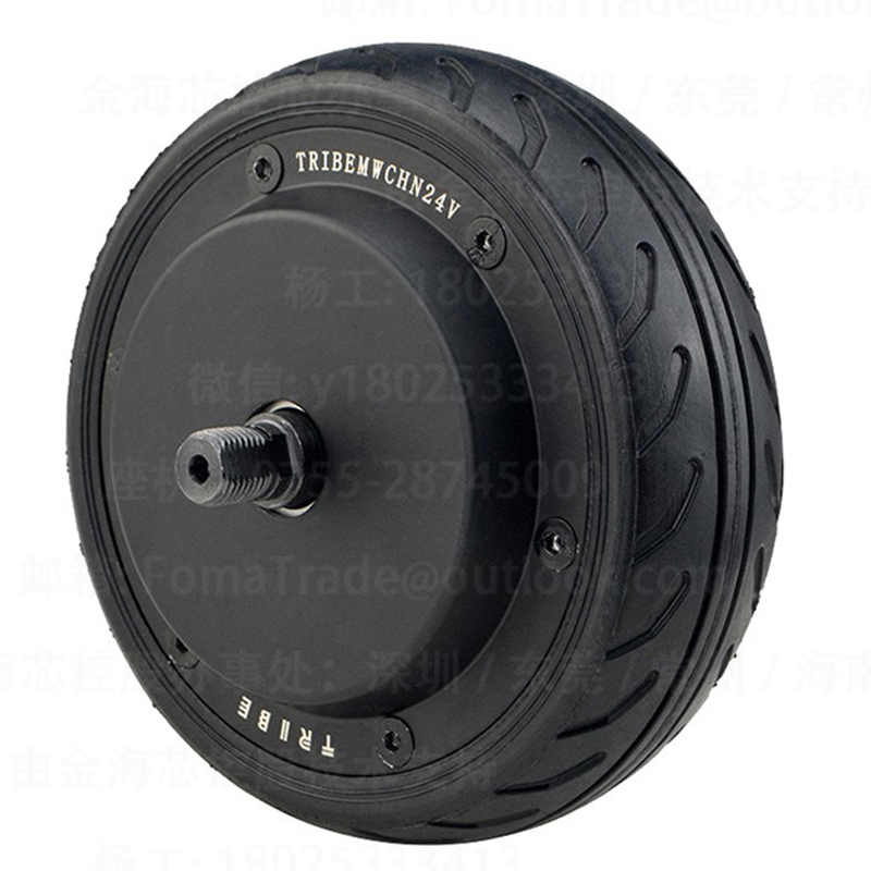
Accurate positioning is the foundation of a successful motor installation. The 5-inch motor has a diameter of 130mm and an opening width of 68mm. These dimensions are critical for stable fixation. Use a measuring tool to ensure the installation location precisely matches these specifications. This precise positioning reduces vibrations and noise during operation, significantly enhancing the reliability of the equipment.
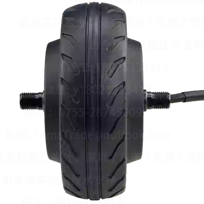
The double-sided threaded shaft is an important component of the 5-inch motor. Proper locking is essential to prevent loosening and abnormal noises, thereby enhancing the structural strength of the motor. Use a torque wrench to tighten the nuts on the threaded shaft to the specified torque value (usually around 30-40 N·m). Applying a thread locker can also provide additional security and prevent the nuts from loosening due to vibrations.
Expert Advice: Regularly check the tightness of the threaded shaft during the motor's operation to ensure long-term stability.
The Hall sensor is a key component for speed regulation accuracy. Proper calibration ensures the motor operates at the desired speed. First, power on the motor and let it run at a low speed. Use a multimeter to measure the output voltage of the Hall sensor. Adjust the position of the Hall sensor according to the measurement results until the output voltage reaches the specified range (usually between 0.5-4.5V). This calibration process improves the motor's speed regulation accuracy and reduces speed fluctuations.
After the installation and calibration are complete, it's time for no-load debugging and load testing. During no-load debugging, power on the motor and let it run for about 10-15 minutes. Observe the motor's operation status, including speed, noise, and vibration. Check for any abnormal phenomena such as speed fluctuations or startup stuttering. If any issues are found, stop the motor immediately and troubleshoot.
Once the no-load debugging is successful, proceed with the load testing. Gradually increase the load on the motor and observe its performance under different loads. Monitor parameters such as current, temperature, and speed. Ensure the motor can operate stably under the rated load. This testing process helps identify potential problems and optimize the motor's performance.
During the installation and operation of the 5-inch motor, you may encounter some common faults. Here are some typical problems and their solutions:
| Fault | Cause | Solution |
|---|---|---|
| Speed fluctuations | Loose connections, incorrect Hall sensor calibration | Check and tighten connections, recalibrate the Hall sensor |
| Startup stuttering | Low voltage, mechanical blockage | Check the power supply voltage, remove any mechanical blockages |
To ensure the long-term stable operation of the 5-inch motor, here are some practical tips:
By following this comprehensive guide, you can master the installation and debugging process of 5-inch motors, reduce the返修 rate, extend the service life of the equipment, and significantly improve the reliability of your operations. Don't miss out on this opportunity to enhance your motor installation skills! Click here to learn more.


