A low-voltage three-electric system refers to the integrated powertrain foundation built around three tightly coupled modules: a BLDC hub motor, a drive controller, and an energy battery pack. In low-voltage applications (common in light electric mobility and compact equipment), the system’s real-world performance depends less on any single component and more on how well these three modules are matched and coordinated.
As a B2B manufacturer and solution-oriented supplier, Shenzhen Jinhaixin Holdings Co., Ltd focuses on the design, R&D, customization, production, and sales of low-voltage three-electric systems—supporting engineers and procurement teams who need clear module boundaries, stable interfaces, and reliable system-level operation.
In a low-voltage platform, available voltage headroom is limited. That means current, thermal load, wiring, and control strategy become more sensitive. A motor with strong torque potential can still feel weak if the controller’s current capability or control algorithm is mismatched, and even a capable controller cannot sustain output if the battery pack and BMS cannot deliver stable power.
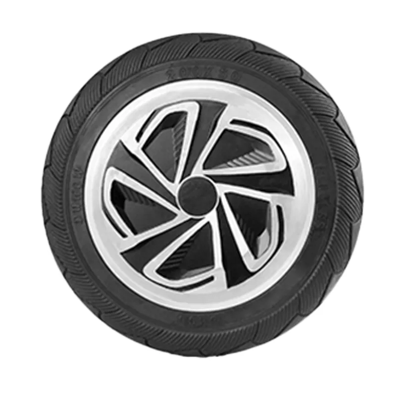
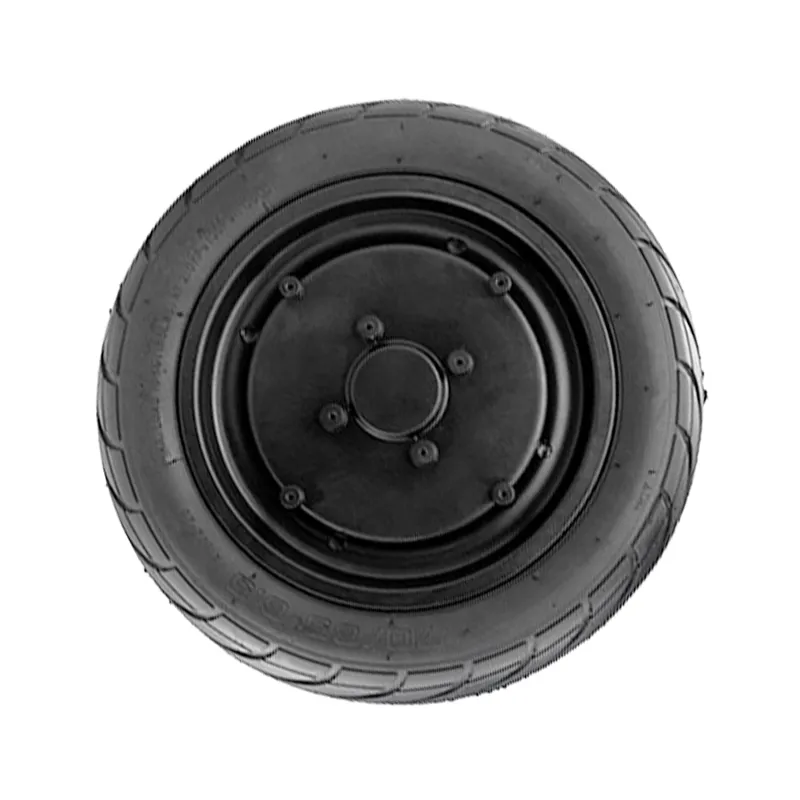
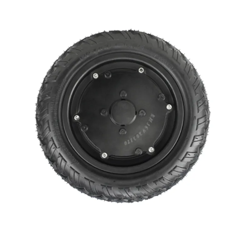
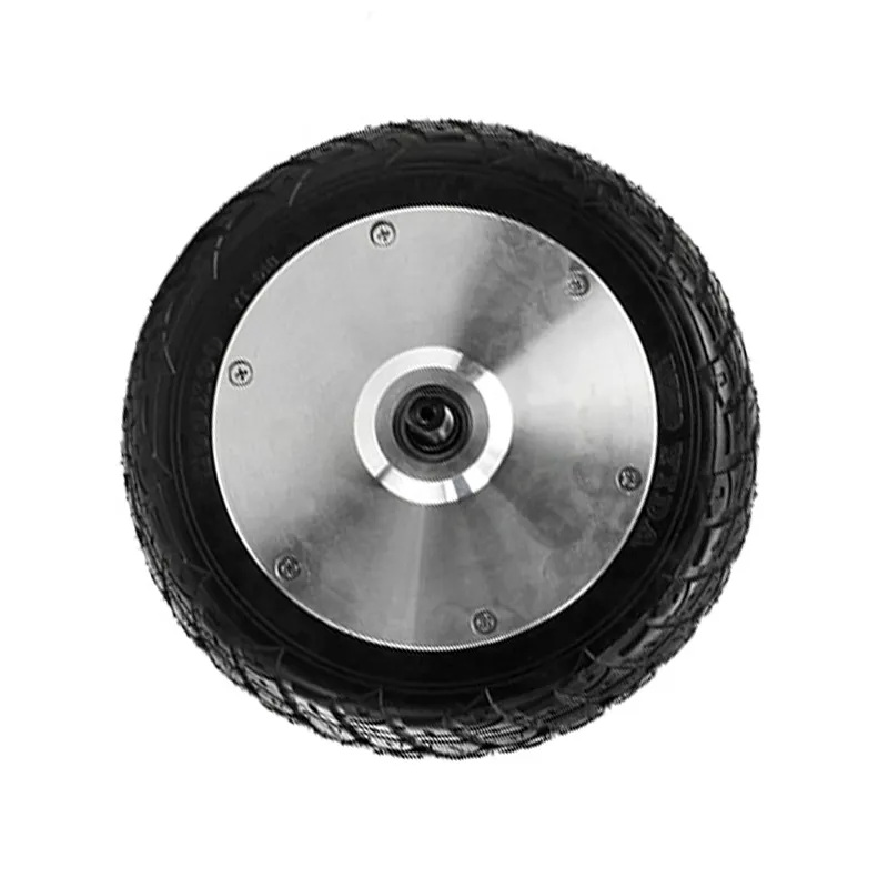
The BLDC hub motor is the actuator that produces torque at the wheel. Its electromagnetic design and mechanical structure directly influence torque density, thermal behavior, and durability.
The drive controller is the system’s “brain and power converter.” It interprets commands and sensor feedback, then modulates current to the motor phases to achieve the desired torque and speed.
The energy battery pack provides the system’s electrical energy and determines how much power can be delivered continuously and during peak demand—while maintaining safety boundaries through pack design and management logic.
From a B2B engineering standpoint, a “good” three-electric system is one where interfaces are clear, limits are coordinated, and thermal and electrical margins are designed at the system level—not patched component by component.
When evaluating or customizing a low-voltage three-electric system, it helps to align on a shared checklist. This reduces integration risk and accelerates specification lock.
| Area | What to Align On | Why It Matters |
|---|---|---|
| Motor–controller match | Control method, sensor/feedback compatibility, phase wiring, current capability | Smooth operation, startup torque, stable commutation, reduced heating |
| Battery–controller match | Voltage range, peak/continuous discharge ability, undervoltage strategy | Prevents power drop, nuisance cutoffs, and stress on components |
| Protection coordination | Overcurrent/overtemp thresholds, derating logic, fault behavior | Predictable response in extreme conditions; easier troubleshooting |
| Thermal & packaging | Heat paths, enclosure constraints, cable routing, mounting interfaces | Sustained performance and serviceability in real installations |
| Application profile | Load, duty cycle, target feel (response/smoothness), environment needs | Ensures the system is tuned for your use case, not just bench specs |
Low-voltage architectures are widely adopted in applications that prioritize compact integration, manageable electrical safety boundaries, and efficient power delivery for light-to-medium loads.
Actual suitability depends on duty cycle, load profile, environment, and integration constraints.
Shenzhen Jinhaixin Holdings Co., Ltd provides system-centric support spanning BLDC hub motors, drive controllers, and energy battery packs, with a focus on interface clarity and manufacturable customization.
For effective technical discussion, prepare your target application profile (load, duty cycle, environment), packaging constraints, and preferred control/command interface—so the motor–controller–battery match can be evaluated as a single system.
If you are comparing suppliers or reviewing a design, ask “what limits the system first?” In low-voltage platforms, limitations often come from current handling, heat, and voltage stability under load. Addressing these at the system level helps avoid over-specifying one module while unintentionally bottlenecking another.
By framing requirements around the low-voltage three-electric system—not just a motor, controller, or battery in isolation—B2B teams can improve integration efficiency and reduce iteration cycles during selection and customization.