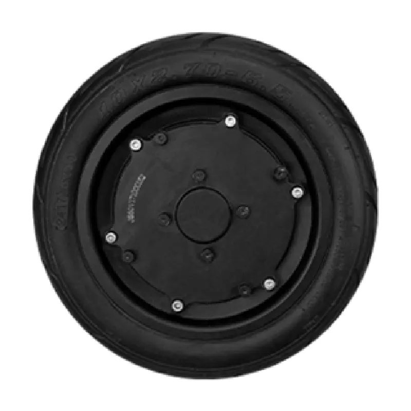
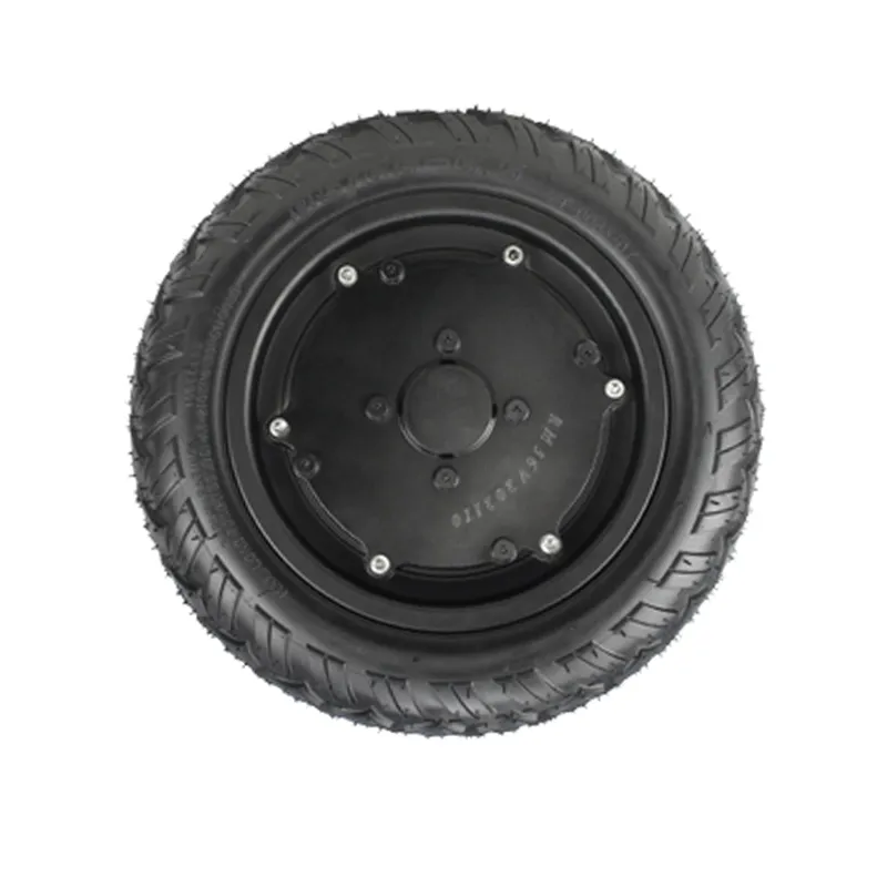
A low-voltage three-electric (e-powertrain) system is the coordination of three core modules: an energy battery pack (DC power source), a drive controller (power conversion + control), and a brushless hub motor (actuator that outputs wheel torque). Understanding how these parts work together helps engineers and procurement teams communicate requirements clearly during early-stage solution discussion.
This introductory page is provided by Shenzhen Jinhaixin Holdings Co., Ltd (Shenzhen Jinhaixin Holdings Co., Ltd), a B2B manufacturer focused on low-voltage three-electric system design, R&D, customization, production, and sales, including hub motors, controllers, and energy battery packs.
In many light electric mobility and end-device applications, the powertrain is built around a low-voltage DC bus. The “three-electric” concept focuses on the smallest complete chain that turns stored electrical energy into controllable mechanical output:
In practice, performance and stability depend on how these three modules are matched and how power flow and signal flow are coordinated.
Battery pack provides DC energy → controller shapes and commands current/voltage to the motor → hub motor outputs controllable torque.
For early-stage communication, it is often more useful to describe the required torque/speed behavior, power limits, and operating conditions than to jump directly into model numbers.
The energy battery pack outputs DC power. The drive controller draws that power, performs conversion/regulation (e.g., DC-to-3-phase drive stage), and delivers controlled electrical energy to the brushless hub motor windings. The motor then converts it into mechanical torque at the wheel.
The system receives a demand signal (such as throttle, speed command, or torque request) and converts it into a motor control target. The controller uses feedback (typical examples include speed/position sensing or inferred state) to time commutation and regulate current, enabling stable start-up, acceleration, cruising, and deceleration behaviors under varying load conditions.
A practical low-voltage three-electric system is not only about motion—it is also about protection logic. The controller typically enforces limits and reacts to abnormal conditions (for example, over-current/under-voltage/over-temperature triggers depending on design). System-level stability comes from appropriate matching of battery capability, controller limits, and motor load requirements.
Coordination logic in one line: the battery pack provides DC energy, the controller manages voltage/current and commutation based on demand and feedback, and the brushless hub motor converts that controlled electrical energy into wheel torque.
When discussing a low-voltage e-powertrain, teams often start from the end-device goal (required motion and operating conditions) and then translate it into three-electric requirements:
As an integrated B2B manufacturer specializing in low-voltage three-electric systems, brushless hub motors, drive controllers, and energy battery packs, Shenzhen Jinhaixin Holdings Co., Ltd supports projects where customers need a clear, coordinated solution rather than isolated components. The company provides design, R&D, customization, manufacturing, and supply to help align motor-controller-battery coordination with the customer’s application needs.
Requirements clarification may include integration constraints, expected control behavior, operating environment, and coordination boundaries between the battery pack, controller, and hub motor—so the system can be designed and produced consistently under an established quality management approach.
For solution communication, describing your end-device goals and constraints first often leads to faster alignment on a suitable motor + controller + battery pack coordination approach.
Need to align a low-voltage three-electric architecture for your application? Share your target torque/speed behavior, duty cycle, and integration constraints for an efficient technical discussion.
Hub Motor • Controller • Battery Pack Coordination