What to Evaluate When Selecting a Low-Voltage Electric Drive System for Machinery
Shenzhen Jinhaixin Holdings Co., Ltd explains the key parameters to evaluate when selecting a low-voltage electric drive system for machinery—covering BLDC hub motor sizing, controller matching, and battery pack configuration for a structured pre-assessment.

Selecting a low-voltage electric drive system for machinery is a parameter-driven decision: application loads, torque/speed demand, controller strategy, and battery limits must align as one system. This page provides a structured pre-assessment checklist—focused on BLDC hub motor sizing, drive controller matching, and battery pack configuration—to help machinery OEMs and project teams reduce iteration risk before sampling and integration.
Brand context: Shenzhen Jinhaixin Holdings Co., Ltd (Shenzhen Jinhaixin Holdings Co., Ltd.) designs and supplies low-voltage “three-electric” components—BLDC hub motors, drive controllers, and energy battery packs—and supports parameter-based pre-assessment for system matching across machinery applications.
1) Start from the application scenario (define the boundary conditions)
A low-voltage electric drive selection should begin with a clear scenario definition. This prevents under/over-sizing and helps establish realistic voltage/current limits, thermal margins, and packaging constraints.
- Machine type & duty profile: continuous operation vs. intermittent cycles, typical cycle time, start/stop frequency.
- Environment: ambient temperature range, dust/water exposure, vibration, and expected corrosion conditions.
- Mobility & speed envelope: target travel speed range, gradeability, and maneuvering requirements (e.g., low-speed high-torque control).
- Electrical boundary: preferred system voltage level (low-voltage domain), available charging interface, and allowed peak current.
- Mechanical interfaces: available mounting space, wheel/hub constraints (for hub motors), cable routing, and connector constraints.
2) Load, torque, and speed: the core sizing variables
For machinery electrification matching, the most common mismatch occurs when torque demand (especially at launch/low speed) is not aligned with controller current capability and battery peak discharge. Establish the load model first, then translate it into torque/speed points.
What to quantify (minimum set)
- Payload & vehicle mass (curb + payload) and wheel radius / effective rolling radius.
- Target traction / drawbar pull at key points (start, climb, steady travel).
- Speed targets at key points (creep speed, nominal travel speed, max speed).
- Grade and rolling resistance assumptions (or measured values where possible).
Selection implications
- Peak torque vs. continuous torque: define both; continuous torque links to thermal design and cooling assumptions.
- Speed range: impacts motor KV/back-EMF matching and controller voltage headroom.
- Acceleration / transient events: determine peak current requirements for controller and battery pack.
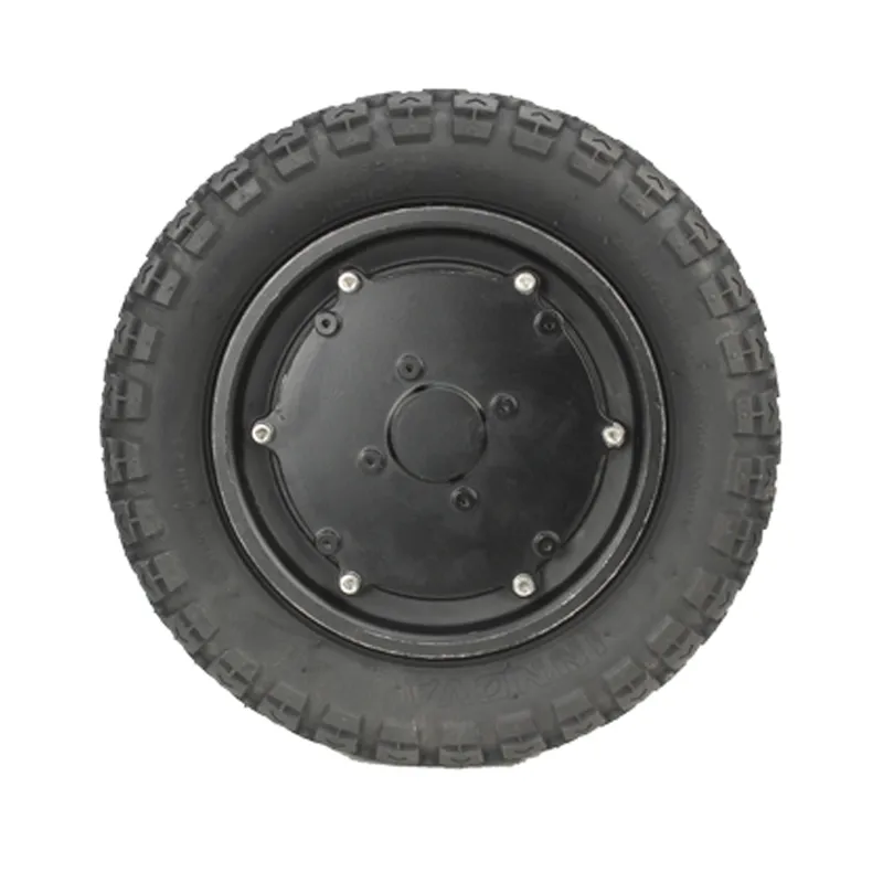
3) BLDC hub motor parameters to check (mechanical + electrical)
When a BLDC hub motor is part of the architecture, confirm both the mechanical integration and the electromagnetic operating window. A motor that “fits” electrically but not physically (or vice versa) will stall the project.
| Parameter group |
What to confirm |
Why it matters |
| Torque / power |
Continuous torque, peak torque, rated/peak power, efficiency range |
Links directly to duty cycle performance and thermal stability |
| Speed capability |
Rated speed, maximum speed, back-EMF characteristics (KV/Ke) |
Determines whether the motor can reach target speed under system voltage limits |
| Voltage/current window |
Nominal voltage, max phase/bus current (as applicable) |
Must match controller output and battery peak discharge capability |
| Sensing / commutation |
Hall sensors vs. sensorless, encoder needs, signal levels |
Affects low-speed controllability, start torque, and controller compatibility |
| Thermal & protection |
Temperature sensing, insulation, ingress protection expectations |
Prevents derating surprises and improves system reliability under load |
| Installation / packaging |
Mounting dimensions, axle/bolt pattern, cable exit direction, connector type |
Ensures manufacturability and reduces rework in mechanical design |
Practical note: For hub-motor machinery, confirm how the motor’s continuous torque aligns with your real duty cycle—continuous performance is typically the limiting factor in long-run operation.
4) Drive controller matching: control, current, and protection
The controller is the system’s “decision center.” Matching a controller to a BLDC hub motor is not only about nominal voltage—it also involves current headroom, control modes, I/O integration, and protection strategy.
Key controller parameters to evaluate
- Voltage compatibility: battery voltage range and controller undervoltage/overvoltage thresholds.
- Current capability: continuous and peak current capability (bus and/or phase as specified), and how long peak can be sustained.
- Control requirements: torque control vs. speed control, low-speed stability, start/stop logic, and braking strategy (if applicable).
- Motor feedback support: hall/encoder interfaces and commissioning needs.
- Protection & diagnostics: overcurrent, overtemperature, short-circuit, stall protection, fault reporting, and safe shutdown behavior.
- Integration I/O: throttle/command input type, enable lines, interlocks, and any required communication interface used by the machine.
5) Battery pack configuration: energy capacity and power delivery
Battery selection has two simultaneous goals: energy (how long you run) and power (how hard you can work). In low-voltage systems, peak current can become the primary constraint—so pack design should be checked against the complete torque and duty profile.
Battery parameters to confirm
- Nominal voltage and operating range: must match controller voltage window and motor speed requirements.
- Capacity and expected runtime: based on duty cycle energy consumption assumptions.
- Continuous and peak discharge limits: must support controller demand during launch/climb/transients.
- Thermal considerations: pack heating under load and environmental temperature constraints.
- Protection and monitoring: BMS functions, cell balancing approach, and fault handling logic.
System-level checks
- Peak power chain: battery peak discharge → controller peak current → motor peak torque.
- Voltage sag margin: low-voltage systems are sensitive to sag during peak load; confirm undervoltage behavior.
- Charging and serviceability: charging method, connectors, and maintenance access within the machine layout.
6) Thermal design, protection, and reliability expectations
Machinery applications often run in harsh environments. Establishing thermal and protection requirements early helps avoid late-stage derating and field faults.
- Thermal path: where heat is generated (motor/controller/battery) and how it is dissipated within the machine.
- Protection strategy: define how faults are detected and handled (limp mode, shutdown, reset conditions).
- Ingress and contamination: confirm sealing expectations aligned with the worksite environment (dust, splash, cleaning).
- Wiring & connectors: current rating, strain relief, and routing to reduce failure points under vibration.
7) Installation and packaging compatibility (often underestimated)
Even with correct electrical matching, projects can stall due to packaging conflicts. Validate the mechanical layout at the same time as parameter selection.
- Space claim and mounting interfaces: keep drawings and tolerance stack-ups aligned across motor/controller/pack.
- Cable management: bend radius, abrasion protection, and connector access for assembly.
- Service access: replaceability of controller or battery pack without full disassembly.
How Shenzhen Jinhaixin supports a structured pre-assessment
For machinery OEMs sourcing a low-voltage electric drive system, Shenzhen Jinhaixin Holdings Co., Ltd typically works from your key parameters to help confirm a workable matching direction across BLDC hub motor, drive controller, and energy battery pack. The goal is to clarify boundaries—load/torque-speed points, voltage/current limits, thermal expectations, and installation constraints—before you commit to prototypes.
Information commonly used for matching review
Application & load
Mass/payload, wheel size, speed targets, grade, duty cycle description, environment.
Control & integration
Control mode needs, I/O signals, wiring constraints, diagnostics expectations.
Energy & charging
Desired runtime, charging method, allowable peak current, packaging constraints.
If you are evaluating machinery electrification or upgrading an existing platform, a parameter-based selection review can help align the motor, controller, and battery pack early—reducing rework and improving integration efficiency.




.png?x-oss-process=image/resize,m_fill,h_800,w_800/format,webp)


