

A low-voltage e-powertrain (three-electric) system is typically built around three tightly-coupled modules: the BLDC hub motor (power output), the motor controller (drive control & coordination), and the energy battery pack (power supply). On this page, Shenzhen Jinhaixin Holdings Co., Ltd explains how these modules work together as one system—so B2B teams can plan product combinations, select specifications, and prepare for customization and integration with clearer boundaries.
System view: Treat the hub motor + controller + battery pack as a coordinated set. Better matching helps improve drivability and stability, and reduces integration rework during prototyping and mass production preparation.
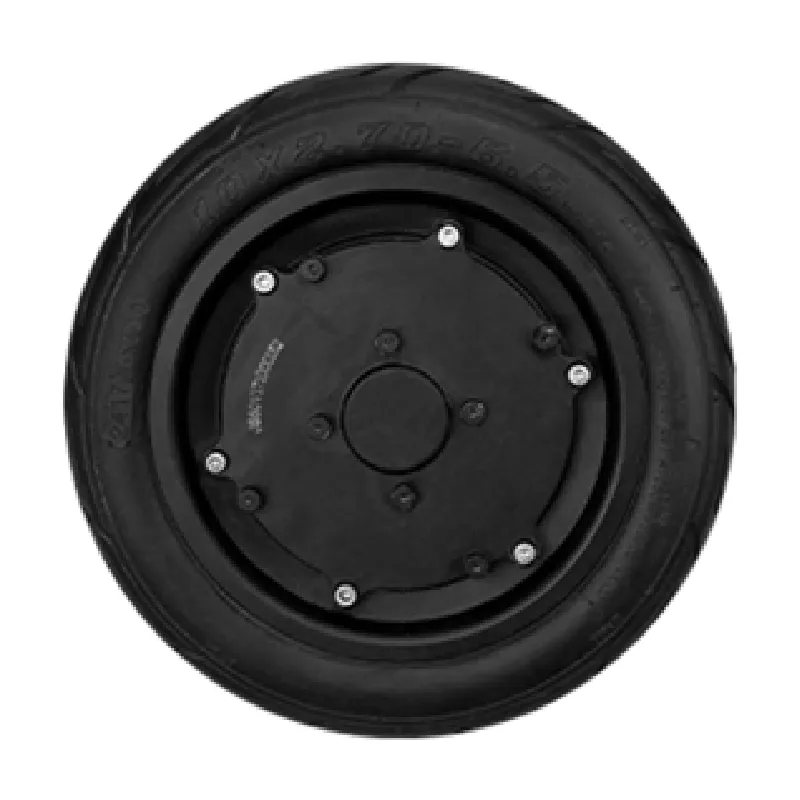
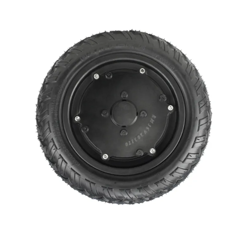
The BLDC hub motor converts electrical energy into mechanical torque directly at the wheel. In a low-voltage e-powertrain, it is the main output element that determines the vehicle’s torque response and speed capability under defined operating conditions.
The motor controller is the coordination center. It interprets command inputs (such as throttle or vehicle control signals) and drives the hub motor with appropriate switching and current regulation. It also manages protection logic to support stable operation.
The energy battery pack provides DC power to the controller and (indirectly) the hub motor. Its voltage platform and current capability define the system’s available electrical power and influence operating time, peak performance, and voltage sag behavior.
Integration tip: Most system issues in prototypes are caused by mismatch (voltage range, peak current, wiring/connector ratings, thermal path, or signal interface assumptions). Starting from a system-level checklist reduces iterations.
When selecting a low-voltage e-powertrain set for B2B projects, it helps to align requirements across the three modules. The table below summarizes common selection dimensions for planning and internal communication.
| Module | What to Confirm | Why It Matters in System Integration |
|---|---|---|
| BLDC hub motor | Operating voltage platform, torque/speed target, mechanical interface, thermal path | Defines vehicle dynamics and mechanical fit; impacts controller tuning and thermal reliability |
| Motor controller | Voltage range, peak/continuous current capability, interface signals, protective logic | Acts as coordination hub; mismatch here often causes unstable drive feel or frequent protection triggers |
| Energy battery pack | Nominal voltage, discharge capability, connector & cable ratings, charging method compatibility | Supports peak load and run time; influences voltage sag and controller operating stability |
| As a complete set | Harness layout, EMC/packaging constraints, environmental protection level, validation plan | Reduces rework from wiring, enclosure, and system-level constraints during pilot builds |
Low-voltage hub-motor powertrains are commonly considered for light electric mobility and industrial applications where compact packaging, simplified driveline architecture, and modular integration are important. Typical B2B evaluation focuses on duty cycle, terrain/load profile, environmental conditions, and manufacturability.
Shenzhen Jinhaixin Holdings Co., Ltd is a manufacturing & trading integrated enterprise focusing on low-voltage three-electric system design, R&D, customization, production, and sales. We supply core modules—including BLDC hub motors, motor controllers, and energy battery packs—and support coordinated planning for customers who prefer a system-level approach.
Headquartered in Shenzhen with production bases in Shenzhen, Dongguan, Changzhou, and Hainan, we support B2B programs with scalable manufacturing coordination and stable delivery planning.
We operate under a structured quality management approach and efficiency-focused operations to help ensure products remain consistent and reliable across project stages—from evaluation to integration and production readiness.
Note: Exact specifications, protections, and interface options depend on project requirements and final engineering confirmation.
To evaluate a low-voltage e-powertrain system efficiently, prepare the following information for your engineering and sourcing workflow:
With a clear set-level definition—hub motor + controller + battery pack—your team can shorten the path from concept to a validated integration plan, while leaving room for appropriate customization where it matters.





.png?x-oss-process=image/resize,m_fill,h_800,w_800/format,webp)

