
Hub motors look deceptively simple from the outside—until a fleet starts showing vibration, reduced torque, or sudden controller alarms. In real-world applications (e-scooters, utility carts, delivery platforms, mobility devices, and light EV conversions), the most common failures are rarely “random.” They follow patterns tied to load, heat, sealing, and assembly stability. This guide breaks down frequent hub motor issues and the practical steps that maintenance teams can implement to extend service life while keeping performance consistent.
Quick note for maintenance teams: In many field cases, early bearing wear and heat stress show up weeks before a motor fails—usually as subtle noise changes, rising shell temperature, or intermittent power drop under load. Catching these signals early is the cheapest “repair” you’ll ever do.
Most hub motor problems can be grouped into four categories: bearing wear, heat accumulation, power attenuation, and structural loosening. Each has a typical “cause chain”—and once you understand it, prevention becomes systematic instead of reactive.
| Symptom | Likely Root Cause | What to Check First | Risk if Ignored |
|---|---|---|---|
| Grinding / rumble noise | Bearing pitting, contamination, misalignment | Axial play, seal condition, grease leakage | Rotor-stator contact, sudden seizure |
| Shell too hot to touch | Overload, poor heat path, inadequate duty cycle | Current draw, ambient temp, airflow, mounting | Magnet weakening, insulation aging |
| Power drop under load | Thermal rollback, phase resistance rise, controller limiting | Phase temps, connector heating, hall stability | Escalating heat, wire/connector failure |
| Wobble / repeated spoke or mount issues | Loose fasteners, shaft seating issues, bearing seat movement | Torque marks, fit tolerance, axial retention design | Fatigue cracking, sudden loss of alignment |
Field reference: Many maintenance teams treat noise + temperature rise as the earliest reliable combination. A stable motor that suddenly runs 10–20°C hotter under the same route/load is usually telling you something important.
Bearing wear is the top culprit behind vibration, noise, and progressive efficiency loss in hub motor systems. The “why” usually comes down to three overlapping stresses: mechanical load, contamination, and thermal cycling.
Reference data (maintenance planning): For many small-to-mid hub motors, bearing grease life can drop by roughly 30–50% when average operating temperature increases by 15–20°C. Even if the motor still “runs,” the wear curve becomes much steeper.
Prevention is less about “more grease” and more about keeping alignment stable, contaminants out, and heat under control. Practical steps:
Heat is not just a comfort issue—it’s a reliability multiplier. When a hub motor runs hot for long periods, several things happen at once: winding insulation ages faster, connectors oxidize, magnets can partially demagnetize, and the controller may enforce thermal limiting (which looks like “mysterious power loss”).
Surface temperature: many operators start investigating when the shell repeatedly exceeds 70–85°C after similar trips, especially if the motor previously stabilized at a lower temperature.
Current draw trend: if the system needs more current to achieve the same speed/torque, losses are increasing—often due to heat, bearing drag, or connector resistance.
Duty-cycle mismatch: climbing, stop-and-go routes, or heavy payloads can exceed what the original cooling path can dissipate.
Power attenuation is often blamed on the controller first, but in many cases the motor system is signaling stress. You may see reduced acceleration, fluctuating torque, or inconsistent speed under identical loads.
A delivery fleet reports that vehicles feel “slower” after 20–30 minutes. Inspection shows shell temperature climbing from a historical baseline of 62°C to 82°C. Phase connectors show mild discoloration and the motor has faint rumble at low speed. The corrective action isn’t only electrical: replacing worn bearings and upgrading the connector set reduces drag and heat, restoring stable torque on long routes.
Hub motors experience constant micro-shock. Over time, repeated vibration can loosen interfaces, shift bearing seats, or create axial play that accelerates wear. This is where design choices matter: a motor that maintains stable axial retention tends to stay quiet, cool, and efficient longer.
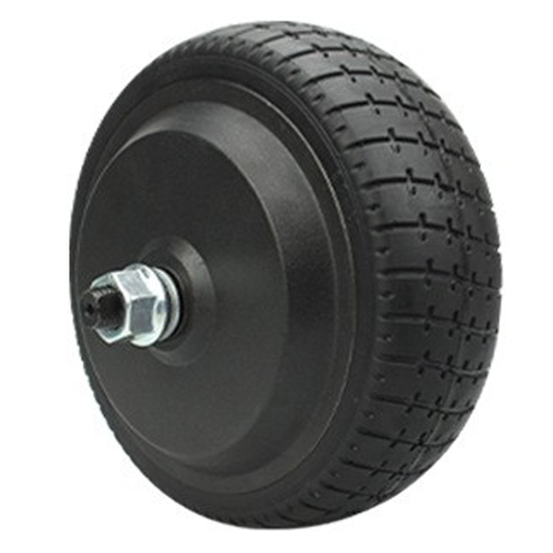
A well-executed single-side press-fit shaft structure can improve stability by concentrating axial retention and minimizing the chance of progressive loosening under cyclic load. In practical terms, this can mean:
Practical expectation: In comparable usage, improving retention stability and sealing often cuts “repeat failure” incidents noticeably—many operators target a 20–40% reduction in vibration-related service tickets after implementing stronger structural retention and a tighter QC loop.
The goal is consistency: the same checks, the same intervals, and records that reveal trends before a failure happens. Below is a lightweight workflow that fits most hub motor maintenance programs.
Step 1: Visual check → seals, cable grommets, corrosion, connector discoloration
Step 2: Mechanical check → axial play, wobble, fastener torque marks
Step 3: Sound & vibration check → compare to baseline (idle + low speed + loaded start)
Step 4: Thermal check → IR reading after standard route/load (record ambient conditions)
Step 5: Electrical quick test → connector heating, phase resistance trend, hall stability (if available)
Step 6: Action decision → monitor / service / replace parts → log results
| Item | Light Use | Commercial / Fleet Use | Trigger for Immediate Check |
|---|---|---|---|
| Seal & cable entry | Every 4–6 weeks | Weekly | Any water exposure / washdown |
| Vibration / noise | Monthly | Every 1–2 weeks | New rumble, squeal, or harshness |
| Thermal trend (IR reading) | Monthly | Weekly | +10–20°C rise under same duty |
| Fasteners / retention | Every 2–3 months | Monthly | Any impact event / wheel wobble |
A basic kit often pays for itself quickly: torque wrench, IR thermometer, dial indicator (axial play), insulation/continuity meter, and a simple inspection log. Consistent records turn “feel-based” maintenance into measurable reliability work.
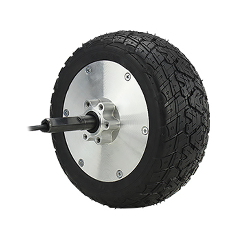
When your application involves repeated shock loads, long duty cycles, or tight installation constraints, the motor’s mechanical stability becomes as important as its peak power. The 8-inch long-axle hub motor “Cyclone” model is designed for practical integration and reliable output, with a structure that prioritizes retention stability and reduced loosening risk—especially valuable for fleet operators and equipment manufacturers who want fewer service interruptions.
Share your load, wheel size, target speed, duty cycle, and installation drawing—then request a matching recommendation and integration notes.
Typical response includes a recommended setup, wiring notes, and maintenance pointers.
For teams aiming to reduce hub motor failures, the most effective strategy is rarely a single fix—it’s a combination of stable structure, controlled heat, clean sealing, and repeatable inspections that keep small issues from becoming downtime.


