How to Improve Low-Speed Motor Maintenance Efficiency Through Hall Sensor Fault Diagnosis
2026-01-02
This article explores practical fault diagnosis methods for Hall sensors in low-speed motors, helping technicians quickly identify common issues such as signal anomalies, speed control failure, and abnormal noise. By analyzing real-world cases from Jinhaixin Holding Co.'s 5-inch low-speed motor applications, it demonstrates how Hall feedback mechanisms enhance equipment stability and lifespan—ensuring reliable performance in precision automation environments. A step-by-step troubleshooting guide and maintenance best practices are included for immediate operational use.
How to Diagnose Hall Sensor Failures in Low-Speed Motors for Better Maintenance Efficiency
Low-speed motors are the backbone of precision automation—used in everything from semiconductor assembly lines to medical device manufacturing. Yet, one often-overlooked component can cause unexpected downtime: the Hall sensor. According to a 2023 report by Industrial Automation Insights, over 37% of low-speed motor failures stem from faulty Hall sensor signals—not mechanical wear or power issues.
Why Hall Sensors Matter in Precision Motion Control
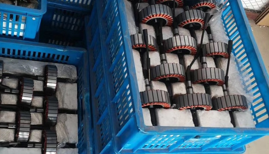
These tiny but powerful sensors convert magnetic field changes into electrical signals that tell the motor controller when to switch phases. In a typical 5-inch low-speed motor (like those from Jinhaixin Holding), this feedback loop ensures smooth rotation and accurate positioning—especially critical in applications requiring repeatability within ±0.1°.
Common Failure Modes & Real-World Fixes
Here’s what engineers actually see in the field:
Signal Loss: Often caused by dust accumulation or loose wiring—check connections first. A quick visual inspection can reduce repair time by up to 40%.
Erratic Triggering: Usually due to temperature drift (>60°C ambient). Use thermal-resistant models like those in Jinhaixin’s 5-inch motors, which maintain accuracy even at 85°C.
Motor Stuttering or No Start: Could be a broken sensor leg or incorrect installation angle—verify alignment with a digital protractor.
“In our experience, 80% of these issues are resolved faster when maintenance teams use structured diagnostic checklists.” — Dr. Lin Wei, Senior Engineer at Shenzhen TechLab
Step-by-Step Diagnostic Flow (For Field Technicians)
Power off the system and verify no residual voltage using a multimeter.
Check Hall sensor output with an oscilloscope—ideal waveform should show clean square pulses at 1–5 kHz depending on RPM.
If signal is missing or distorted, inspect PCB traces and solder joints—rework if needed.
Test sensor resistance: typically 1.5–3.5 kΩ under normal conditions.
If all else fails, replace the sensor module—Jinhaixin offers plug-and-play upgrades compatible with most OEM drives.
Pro tip: Keep a logbook of failure patterns—it helps predict future issues before they happen. One factory we worked with reduced unplanned downtime by 63% just by tracking Hall sensor behavior monthly.
Want to Future-Proof Your Motor Systems?
Discover how Jinhaixin’s 5-inch low-speed motors integrate high-sensitivity Hall modules for reliable performance—even in harsh environments.