Home > News > 8-Inch Unilateral-Shaft Hub Motor Maintenance & Troubleshooting Guide | WINAMICS - Shenzhen Jinhaixin Holdings Co., Ltd

Maintenance & Troubleshooting Workflow for WINAMICS 8-Inch (Ø200 mm, 84 mm Tire) Unilateral-Shaft Hub Motor

2026-10-02
Shenzhen Jinhaixin Holdings Co., Ltd (WINAMICS) provides a practical maintenance and fault-diagnosis workflow for the 8-inch (Ø200 mm) unilateral-shaft hub motor with 84 mm tire width, covering routine inspections, electrical connections, mechanical/environment checks, symptom-based troubleshooting, and escalation guidance to reduce misoperation risk and improve uptime.

This page provides a practical, field-ready maintenance and troubleshooting workflow for the WINAMICS 8-inch (Ø200 mm, 84 mm tire width) unilateral-shaft conventional hub motor, designed and manufactured by Shenzhen Jinhaixin Holdings Co., Ltd. It is intended for maintenance engineers, technical support teams, and equipment operators working with small vehicles and recreational equipment (e.g., compact karts and similar platforms).

Note: Where inspection values, lubrication points, and service intervals are involved, follow the applicable product technical documentation and your actual system configuration (motor + controller + battery pack). Avoid on-site disassembly when not recommended and escalate to qualified personnel as needed.

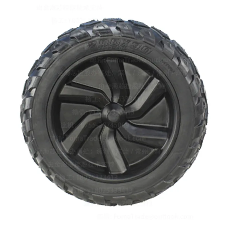
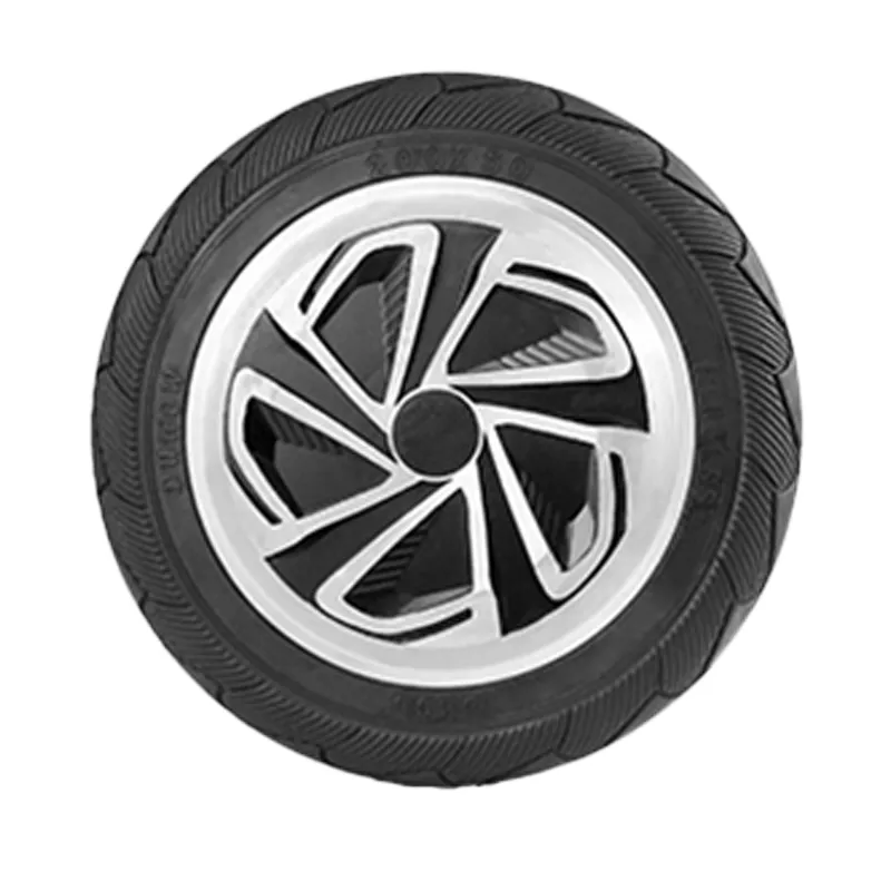
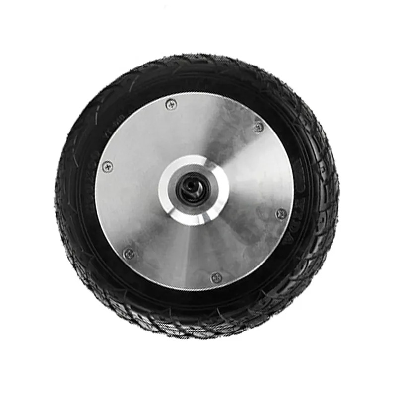
WINAMICS 8-inch Ø200 mm unilateral-shaft hub motor with 84 mm tire width, shown for maintenance and troubleshooting reference

Product identification

  • Type: 8-inch unilateral-shaft conventional hub motor
  • Wheel diameter: Ø200 mm
  • Tire width: 84 mm
  • Brand: WINAMICS

This model is designed for stable operation and efficient power transmission, with a unilateral-shaft structure intended to simplify installation and reduce rework under correct fitment.

Safety & Preparation (Before Any Inspection)

  • Power isolation: stop the equipment, remove the key/enable signal, and isolate the battery pack according to your system procedure.
  • Prevent accidental rotation: lift or secure the driven wheel so it cannot unexpectedly move.
  • Visual condition check: look for damaged cables, loose fasteners, abnormal smells, or signs of water ingress before energizing.
  • Use proper tools: insulated tools for electrical work; calibrated torque tools where fastening is involved.
  • Document first: record symptoms, operating conditions, and any recent changes (controller replacement, wiring changes, impact events, load changes).

Routine Maintenance Checklist (Recommended Workflow)

Prioritize checks across motor, controller, battery pack, wiring/connectors, mechanical load, and environment. This reduces misoperation risk and improves uptime.

1) Mounting & Fastening (Mechanical Baseline)

  • Confirm the hub motor is seated correctly and all mounting/fastening points are secure.
  • Inspect the unilateral shaft connection area for loosening, unusual wear marks, or deformation.
  • Check tire fitment and alignment: ensure the 84 mm tire width configuration matches the wheel assembly and does not rub.
  • Spin the wheel by hand (power off): it should rotate smoothly without scraping, binding, or irregular resistance.

Tip: Mechanical looseness at the unilateral shaft interface can amplify vibration/noise and lead to secondary electrical issues (connector fretting, intermittent faults).

2) Harness & Connector Inspection (Most Common Field Issue)

  • Check connectors for looseness, bent pins, discoloration, corrosion, or heat marks.
  • Verify cable routing: avoid sharp bends, pinch points, tire contact, and repetitive flexing at the hub exit.
  • Ensure strain relief is effective and the harness is fixed to prevent vibration-driven wear.
  • Confirm any protective sleeves/boots are intact and properly seated to reduce dust/water entry.

If a fault appears “random” (intermittent start, occasional cut-out), treat connector seating and harness damage as the first priority before deeper component replacement.

3) Operating Temperature, Noise & Vibration Monitoring

  • During operation, monitor temperature rise at the hub/mounting area and compare against your normal baseline.
  • Listen for changes in sound (grinding, clicking, high-pitched whine) and correlate with speed/load.
  • Observe vibration at the unilateral shaft side and wheel assembly; check whether it appears only under acceleration, steady speed, or braking/coast.
  • Record any controller alarms and the conditions when they occur (start-up, hill climb, high load, hot environment).

Abnormal temperature, noise, vibration, and current anomalies often share causes across mechanical load (binding, misalignment), wiring (high resistance contacts), or system mismatch (controller/battery configuration).

4) Environment & Cleanliness (Preventive Reliability)

  • Keep the hub area clean from mud, sand, and fiber debris that may enter seals or abrade cables.
  • After wet operation, inspect for moisture around connectors and dry according to your site procedure.
  • Check for exposure to chemicals or high-pressure wash practices that may compromise protective parts.

Symptom-Based Troubleshooting (Motor–Controller–Battery–Load)

Use the following table as a structured diagnosis guide. Start with non-invasive checks (connections, mounting, load) before considering component replacement.

Symptom Likely check points (priority order) Recommended actions (non-invasive first)
No-start / no rotation Battery pack output & isolation state → enable/command signal → harness & connectors → mechanical binding/load Verify power isolation removed and battery is available; reseat connectors; check for pin damage/heat marks; rotate wheel by hand to rule out mechanical lock; check controller fault indications per your controller manual.
Low power / weak acceleration Mechanical load/tire drag → connector resistance/loose contact → battery sag under load → controller configuration mismatch Inspect tire rub and alignment for Ø200 mm / 84 mm fitment; check harness routing and connector tightness; review whether recent load or gearing changes were introduced; compare behavior against a known-good baseline unit if available.
Overheating / unusual temperature rise Excess load/binding → poor ventilation or hot environment → high contact resistance at connectors → controller/battery mismatch Reduce load and confirm wheel rotates freely; check for connector discoloration or hot spots; ensure cables are not undersupported and vibrating; review duty cycle and ambient conditions; follow your documentation for acceptable temperature limits.
Increased noise / grinding / clicking Mounting/fastening looseness → unilateral shaft interface wear → debris intrusion → tire/wheel interference Stop and inspect mechanical fastening; check unilateral shaft connection area for abnormal marks; clean debris around the hub; confirm tire clearance; if noise persists after external checks, escalate rather than forcing continued operation.
Vibration / rough running Wheel/tire imbalance → loose fastening → misalignment at unilateral shaft side → intermittent connector contact Inspect tire seating and wheel condition; verify mounting torque per your procedure; secure harness to eliminate movement; test under no-load if your equipment allows safe lifting and controlled run.
Intermittent cut-out / random fault Connector seating → harness damage near moving parts → thermal-related contact issues → environment moisture Inspect and reseat connectors; check for cable abrasion at the hub exit and along the frame; look for moisture and corrosion; document the exact moment of failure (temperature, load, vibration) for support escalation.

Graded Handling & Escalation Guidance

  1. Level 1 — On-site routine checks: mounting/fastening, unilateral shaft area, tire clearance, harness routing, and connector seating.
  2. Level 2 — System cross-check: check the motor together with the controller and battery pack as a system; look for configuration changes or mismatched components that can cause current anomalies or overheating.
  3. Level 3 — Controlled verification: if safe and permitted by your site rules, perform a controlled run to reproduce the symptom and log conditions (load, temperature, noise/vibration).
  4. Level 4 — Escalate to after-sales support: if symptoms persist after non-invasive checks, or if you observe heat damage, deformation, or suspected internal issues. Avoid forced operation and avoid unauthorized disassembly.
For efficient support, prepare: product model (8-inch Ø200 mm / 84 mm), application scenario, wiring overview, controller model/configuration summary, symptom description, and photos of connectors and the unilateral shaft connection area.

About WINAMICS & Shenzhen Jinhaixin Holdings Co., Ltd

Shenzhen Jinhaixin Holdings Co., Ltd is an integrated B2B manufacturer focused on low-voltage three-electric systems (motor, controller, and battery pack), providing design, R&D, customization, production, and sales. Under the WINAMICS brand, we supply hub motors and related system components with quality management processes aimed at stable and reliable delivery.

Why this 8-inch unilateral-shaft model

  • Unilateral shaft structure for enhanced stability and efficient power transmission
  • Ø200 mm diameter × 84 mm tire width fitment to reduce rework when properly matched
  • Installation-friendly design for saving labor time in assembly/maintenance

Service boundary (transparent)

  • Guidance is workflow-based and should be adapted to your controller/battery configuration
  • No generic “one-size” numeric limits are provided without your documentation
  • For internal inspection or special tooling needs, escalate to qualified personnel

Request Technical Support / After-Sales Coordination

If you need assistance with maintenance planning, connector/wiring verification, or repeated fault reproduction for the WINAMICS 8-inch unilateral-shaft hub motor, contact Shenzhen Jinhaixin Holdings Co., Ltd with your application details. Our team can coordinate product documentation alignment and support your troubleshooting escalation path.
Name *
Email *
Message *
Recommended Products
8-inch diameter, 200mm tire width, 45mm single-sided pressure shaft cyclone motor
优势特点:1. "Stable Cyclone Power Output": Equipped with a single-sided pressure shaft structure, it enhances operational stability from the root and reduces vibration and component wear during high-frequency use; at the same time, it is tuned to deliver "cyclone-level" strong power, with fast start-up response and linear power output, which not only meets the smooth range requirements of commuter devices, but also adapts to the short-term high-frequency power scenarios of leisure devices. 2. "More Flexible Batch Customization": Supports large-scale batch procurement and parameter customization. Power parameters and shaft length details can be adjusted according to equipment model and usage scenario. Provides standardized B-end procurement services, with dedicated personnel handling the entire process from sample testing to batch delivery, balancing customization flexibility and delivery efficiency. It is the preferred supply chain solution for transportation equipment manufacturers and leisure equipment brands. Installation Instructions 1. Connect the motor to the controller and power supply according to the wiring diagram on the controller. 2.The tire is installed outside the outer rotor hub. 3. When the power cord passes through metal parts, it should be protected by non-metallic products. 4. When the driver is powered on, pay special attention to whether the motor stops rotating, gets stuck, or heats up abnormally quickly. The power must be turned off and on within three seconds to adjust the electrical angle or drive output to prevent motor failure