8-Inch Hub Motor Installation Guide: Standard Procedure, Bolt Tightening Sequence & Troubleshooting
This guide is designed for engineers and equipment manufacturers installing an 8-inch (200 mm) hub motor for the first time. It outlines a standardized, repeatable installation workflow—covering pre-install preparation, alignment and positioning checks, the correct bolt tightening sequence, and compliant electrical wiring practices to achieve stable performance from day one. Built on field-proven experience, it also provides practical debugging tips and on-site troubleshooting methods for common issues such as abnormal noise, overheating, vibration, and inconsistent torque output. Step-by-step visuals and checklists are included to help teams avoid frequent mistakes, reduce rework, and improve delivery efficiency—highlighting the value of a no-secondary-machining approach for saving labor time and lowering manufacturing risk. WWTrade also supports implementation with responsive technical assistance to help users move from setup to reliable operation with confidence.

8-Inch Hub Motor Installation “No-Regrets” Guide: Standard Workflow + Tightening Sequence (With Field-Proven Checks)
This technical guide is written for first-time integrators—equipment manufacturers, automation teams, and engineers who need a repeatable way to install an 8-inch (200 mm) hub motor without rework. It focuses on alignment, fastener tightening order, wiring discipline, and on-site troubleshooting so the motor runs quietly, stays cool, and delivers stable torque from day one. The workflow below matches how many OEMs standardize assembly for faster line takt and fewer returns—especially when the motor is designed for no secondary machining.
Where 8-Inch Hub Motors Are Typically Used—and Why Installation Quality Matters
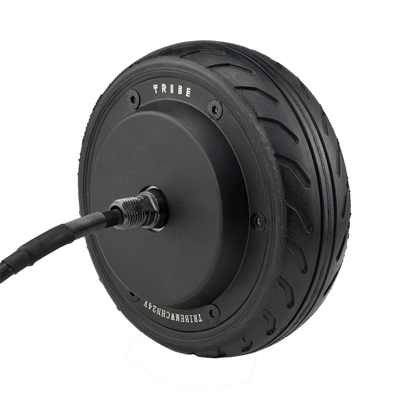
An 8-inch hub motor is commonly selected for compact mobility and automated equipment where integration space is tight and assembly repeatability matters: light AGVs, delivery robots, smart carts, compact electric platforms, and specialized industrial devices. In these applications, the motor becomes both the drivetrain and a structural element, so small installation mistakes can amplify into noise, heat, or premature bearing wear.
Field note: Across common service reports for hub-driven platforms, a large share of “motor problems” are actually integration problems. In many fleets, installers find that misalignment + uneven bolt preload + cable strain account for a meaningful portion of early failures (often observed within the first 50–200 km or 10–30 operating hours, depending on load and environment).
Pre-Installation Checklist (Do This Before You Touch a Bolt)
Tools & Quality Controls
- Calibrated torque wrench (verify calibration cycle; many lines use a 6–12 month interval).
- Thread condition check: confirm no burrs, paint buildup, or damaged threads on mating parts.
- Flatness/cleanliness: mating surfaces must be clean and free of chips; keep runout sources away.
- Fastener policy: confirm grade, length engagement, and whether threadlocker is required by your internal spec.
- ESD & contamination control: protect connectors and prevent metal particles near magnets.
A core benefit many engineers want from an 8-inch hub motor program is “install with standard interfaces—no re-machining”. When the motor and brackets are properly standardized, OEM assembly can often save 20–40 minutes per unit compared with setups requiring secondary drilling, shimming, or repeated alignment attempts (actual savings vary by line maturity and fixture quality).
Positioning & Alignment: The Quiet Motor Starts Here
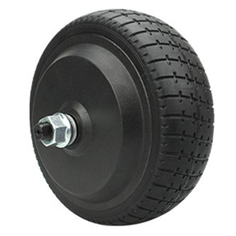
Before tightening, treat the hub motor as a precision rotating assembly. The goal is to ensure the motor seats naturally—without forcing, prying, or “pulling it into place” with bolts. Forcing often creates uneven contact, which shows up later as cyclic noise, unexpected heat, or vibration under load.
Alignment Requirements (Practical Targets)
If your platform has no internal tolerance specification yet, many integrators start with the following practical targets and tighten them as the design matures:
- Mounting face cleanliness: zero trapped debris; even small chips can introduce measurable runout.
- Concentricity mindset: avoid lateral pre-load; the motor should sit flush before torque is applied.
- Cable exit orientation: plan routing so there is no bending stress at the grommet/connector.
Note: The exact alignment tolerances depend on your mechanical stack, wheel design, and bearing configuration. If you have a drawing-level spec, follow it first.
Standardized Installation Steps (Repeatable on the Line)
Step-by-Step Workflow
- Dry-fit the motor to verify natural seating (no gaps). If it doesn’t sit flush, stop and inspect surfaces.
- Hand-start all fasteners (never start with power tools). Ensure full thread engagement is smooth.
- Snug in sequence (see tightening order below) to bring the motor evenly to the mounting face.
- Final torque in stages: many lines use a staged approach (e.g., 30% → 60% → 100% of spec) to reduce uneven preload.
- Mark & record: add torque-mark paint or traceability mark per your quality plan.
- Route and secure cables with strain relief; keep clearance from rotating parts and pinch points.
Standardization isn’t just about saving time; it’s about making results predictable across operators. Many OEMs reduce early-stage assembly variation by building a simple work instruction: one page, one sequence, one torque spec table, one inspection checklist.
The Tightening Sequence That Prevents Warping, Noise, and Rework
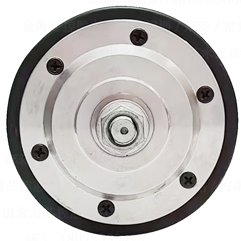
For most hub motor mounting patterns (4, 5, 6, or 8 fasteners), the safest default is a cross-pattern (star pattern). The purpose is to distribute clamp load evenly and avoid “tilting” the motor during seating.
Recommended Practice (General, Not a Substitute for Your Drawing Spec)
- Use 3 passes: snug pass → intermediate pass → final pass at specification torque.
- Always finish with a verification loop: repeat the sequence once at final torque to confirm no bolts relaxed as others tightened.
- Avoid “one-bolt-to-full-torque”: this is a common cause of uneven seating and later vibration complaints.
- If using threadlocker: keep application consistent and avoid contaminating bearing areas.
In practice, teams who implement staged torque and cross-pattern tightening often see fewer “mystery noises” and fewer repeat disassemblies during end-of-line tests. It’s one of the simplest process controls with high ROI.
Electrical Wiring Discipline: Stability, Safety, and Faster Debugging
Wiring issues can mimic mechanical defects. A clean wiring standard reduces intermittent faults and makes commissioning much faster. For typical hub motor systems (BLDC/PMSM), stability depends on consistent phase wiring, reliable hall/sensor signals (if used), and proper shielding/grounding strategy.
Wiring Rules Many OEMs Enforce
- Strain relief first: clamp/anchor the cable so the connector never carries mechanical load.
- Separate power and signal: keep phase wires away from sensor lines to reduce EMI coupling.
- Respect bend radius: avoid tight bends near the motor exit; repeated flexing drives early insulation fatigue.
- Ingress protection awareness: ensure grommets and seals are seated; water ingress often becomes a “random” fault weeks later.
- Labeling: phase order and sensor connector labeling reduces commissioning time significantly, especially in multi-wheel platforms.
Commissioning & Debug: Fast Tests That Catch 80% of Problems
A short, disciplined commissioning routine prevents long “trial-and-error” sessions later. The following tests are commonly used in factories and on integration benches. They are designed to be quick, repeatable, and traceable.
| Test |
What It Reveals |
Typical “Stop and Fix” Signals |
| No-load spin at low RPM |
Basic alignment, rubbing, abnormal noise |
Cyclic scraping, periodic vibration, connector tugging |
| Direction check |
Phase order / controller mapping |
Reverse rotation vs. expected; unstable startup |
| Low-speed load test |
Torque delivery, mechanical seating under load |
Knocking under load, fastener loosening signs |
| Thermal spot-check |
Heat rise behavior, friction/overcurrent hint |
Rapid heating in minutes at light load |
If your project requires data discipline, a lightweight log (unit ID, torque confirmation, test results, and any deviations) can improve field feedback loops and reduce repeat defects across batches.
Common Issues & On-Site Troubleshooting (Noise, Heat, Vibration)
Symptom → Likely Cause → First Checks
- Clicking or cyclic scraping: often contact/rubbing or uneven seating → recheck flush fit, inspect debris on mounting face, verify cable clearance.
- High-frequency whine at low speed: sometimes control parameters or sensor mismatch → verify hall/encoder wiring, check controller settings and phase mapping.
- Fast temperature rise at light load: friction or overcurrent → check bearing preload sources, confirm torque sequence, verify current limits and mechanical drag.
- Vibration under load only: uneven clamp load or bracket flex → verify staged torque process, inspect bracket stiffness and fastener engagement depth.
- Intermittent cutout: connector strain or EMI → ensure strain relief, separate power/signal, confirm shielding/ground reference strategy.
Experienced engineers usually start troubleshooting from the simplest variables that change between “good unit” and “bad unit”: assembly sequence, bolt preload consistency, and cable routing. That mindset resolves many issues before deeper electrical diagnostics are needed.
Operator-Ready Checklists (Installation + Debug)
Installation Checklist
- Mounting surfaces cleaned and inspected (no chips/paint buildup).
- Motor seated flush by dry-fit (no forced alignment).
- All bolts hand-started; correct length and engagement confirmed.
- Cross-pattern tightening used with staged torque passes.
- Torque marks applied; traceability recorded if required.
- Cable strain relief installed; safe clearance to rotating parts ensured.
Debug Checklist
- No-load spin test passed (no rubbing, stable sound).
- Rotation direction confirmed; controller mapping verified.
- Light-load test passed; no vibration spike under torque.
- Thermal spot-check within expected rise for your duty cycle.
- Connectors locked; no cable movement during suspension/steering travel (if applicable).
Why “No Secondary Machining” Changes Project Delivery Speed
In many real integration projects, schedule slips come from small mechanical surprises: hole patterns that need rework, shims added late, or alignment that depends on a single skilled operator. When an 8-inch hub motor is engineered for standardized interfaces, it can reduce these surprises—and make performance more consistent across batches.
WWTrade supports OEM and engineering teams with integration-oriented documentation, fast technical feedback, and after-sales practices designed to shorten the loop between bench test and stable mass assembly—especially for teams scaling from pilot builds to repeat production.
Want a Cleaner, Faster Build? Get the 8-Inch Hub Motor Installation Pack
Request a practical integration package for your platform: recommended tightening sequence, wiring notes, commissioning checklist, and common troubleshooting paths—so your first build behaves like your hundredth.
Download the 8-Inch Hub Motor Installation & Debug Kit
Ideal for OEM engineers, system integrators, and manufacturing teams standardizing assembly and quality checks.


