


Phase wires (U/V/W)
Keep phase wires as short as practical, use appropriate gauge, and avoid running them parallel to sensor lines for long distances. If crossing is necessary, cross at near 90° to reduce coupling.

For OEM engineers and equipment manufacturers, installing an 8-inch hub motor can look deceptively simple—until vibration, abnormal heat, loose fasteners, or intermittent sensor errors appear during commissioning. In field service reports across light mobility and compact industrial platforms, over 60% of early-stage hub motor issues trace back to installation-related factors: misalignment, uneven bolt preload, pinched harnesses, and grounding mistakes.
This guide presents a repeatable, shop-floor-friendly process—including a proven tightening order, wiring norms, and a fast troubleshooting logic—so first-time installers can hit stable performance without rework and keep delivery schedules intact.
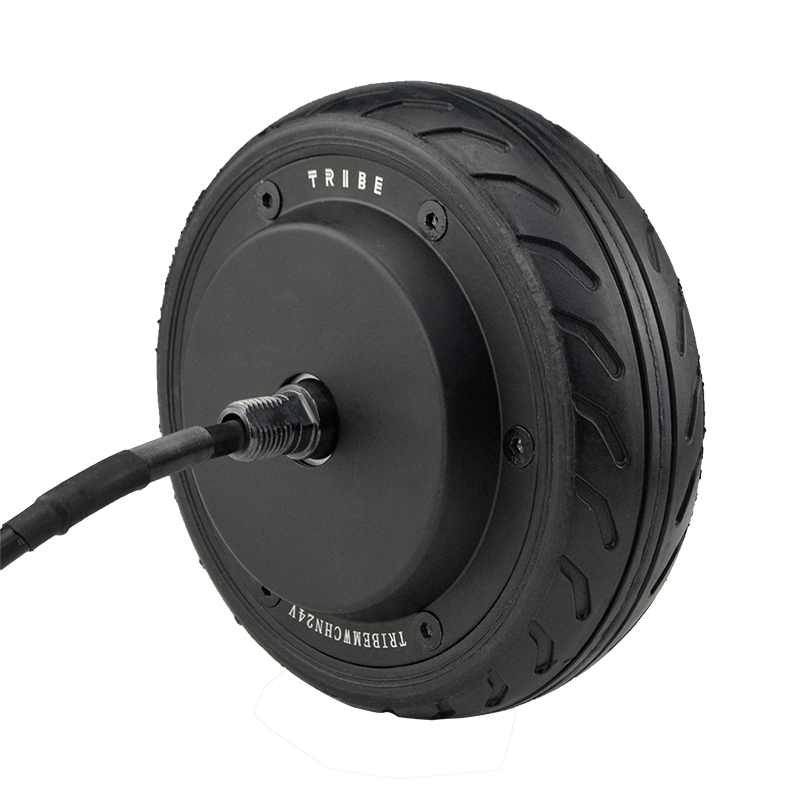
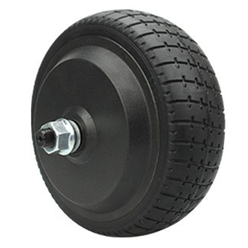
The 8-inch (200mm) hub motor format is widely selected for compact systems where packaging space is limited and torque delivery must be direct: small AGVs, service robots, smart carts, light scooters, and customized mobility platforms. Because the motor is integrated into the wheel, the assembly becomes both a power unit and a structural component. That dual role means installation defects are amplified into mechanical noise, bearing stress, encoder drift, or reduced range.
Before mounting, a quick verification prevents most “mystery” faults during testing. Experienced integrators typically spend 10–15 minutes here to save hours later.
If an 8-inch hub motor is installed with slight angular misalignment, the platform can pass a low-speed test yet fail under load or at higher RPM. A pragmatic alignment approach:
Place the hub motor into position without final torque. Confirm it sits flush with no rocking. Any “springy” feel often points to debris, burrs, or a slightly warped bracket.
Ensure the axle/cable exit faces the planned routing direction. Avoid routing that forces the harness to twist during steering or suspension travel.
Rotate the wheel through its full motion envelope (steer/suspension if applicable). Verify clearance to guards, brackets, and sensor mounts, especially near the rotating sidewall.
Many OEMs adopt a simple acceptance target: if vibration becomes noticeable above a given speed threshold (often 10–15 km/h for compact platforms), the first suspects are alignment and uneven preload—not the motor itself.
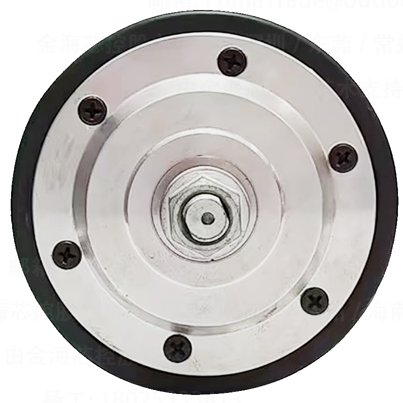
Uneven tightening is a leading cause of early loosening, rotor rub, or bearing preload stress. The solution is not “more torque,” but a consistent sequence and progressive torque steps. A robust workflow used by integrators:
Note: Final torque depends on bolt size, grade, joint material, and bracket design. Use the motor supplier’s drawing/spec and your equipment’s DFMEA requirements as the authority.
Hub motor wiring issues tend to show up as intermittent cut-outs, unstable speed control, or abnormal heat. A clean, standards-aligned wiring approach focuses on separation, shielding, and strain relief.
Keep phase wires as short as practical, use appropriate gauge, and avoid running them parallel to sensor lines for long distances. If crossing is necessary, cross at near 90° to reduce coupling.
Treat sensor wiring as “noise-sensitive.” Use shielding if specified, ensure connector pins are fully seated, and secure the harness so vibration does not micro-fret contacts over time.
Use a defined grounding strategy (star ground where appropriate). Add abrasion protection at pass-through holes. If your system runs in humid or dusty environments, seal and strain-relief are not optional.
Commissioning is where hidden installation errors reveal themselves. A staged ramp-up catches problems early and avoids thermal damage.
Many 8-inch hub motor applications aim to keep outer-case temperature in a safe band during sustained duty; a common engineering reference is to investigate if case temperature trends beyond roughly 70–85°C depending on insulation class, ambient conditions, and enclosure design.
When issues appear, a structured diagnosis prevents random part swapping. The table below reflects common on-site patterns seen during first builds and pilot runs.
| Symptom | Most likely installation causes | On-site checks (quick) |
|---|---|---|
| Abnormal noise / rubbing | Misalignment, uneven bolt preload, bracket deformation | Loosen and re-seat; re-torque in star pattern; check for gaps; rotate by hand |
| Vibration at speed | Runout/tolerance stack, uneven mounting, tire/wheel imbalance | Check seating and runout; verify fasteners; inspect wheel condition |
| Overheating under load | High resistance connector, undersized cables, mechanical drag | Check connector temperature; measure voltage drop; confirm free rotation |
| Jerky start / unstable speed | Hall/encoder connector not seated, signal noise, wrong phase order | Re-seat signal connector; separate routing; verify phase/sensor mapping |
| Intermittent cut-out | Harness strain, pinched cable, poor grounding | Wiggle-test harness safely; inspect pinch points; verify grounding continuity |
In many OEM projects, schedule risk comes less from motor selection and more from integration surprises—custom shims, re-drilling, bracket rework, repeated test loops. A hub motor designed for standardized installation can reduce these surprises. In typical small-batch builds, avoiding secondary machining may save 1–3 hours per unit depending on your fixture setup and inspection process, while also reducing tolerance stack risks that show up later as vibration or premature wear.
WWTrade supports equipment makers with documentation-first integration: installation notes, wiring guidance, and after-sales response designed around real commissioning questions—so engineers can move from prototype to repeatable production with fewer “unknowns.”
Get a practical integration bundle (mounting checklist, tightening sequence notes, wiring do’s & don’ts, and commissioning pointers) tailored to your platform’s duty cycle and environment.
Request 8-inch hub motor installation & commissioning supportTypical response time for engineering questions: within 24–48 business hours (project-dependent).


