8-Inch Hub Motor Installation Guide: Step-by-Step Setup, Wiring, and Commissioning Tips
This tutorial provides a standardized, field-proven workflow for installing and commissioning an 8-inch single-side press-fit axle hub motor, helping new engineers and equipment builders avoid common setup mistakes. It covers pre-installation preparation (tools, workspace, and safety checks), precise positioning and alignment, recommended fastening sequence, and correct electrical wiring practices to ensure stable performance from the first power-up. Practical troubleshooting guidance is included to speed up fault isolation, along with a hands-on checklist for final verification. The guide also highlights the time-saving advantage of a no secondary machining design and introduces WWTrade’s support-oriented service approach for smoother deployment and long-term reliability.

8-Inch Hub Motor Installation (Single-Side Press-Fit Shaft): A Practical, Standardized Workflow That Prevents Costly Mistakes
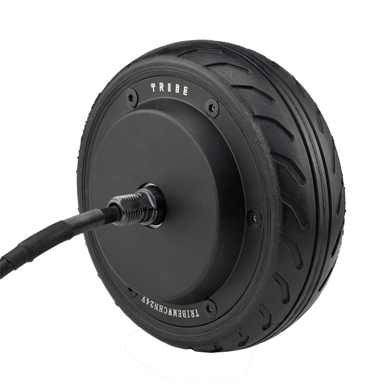
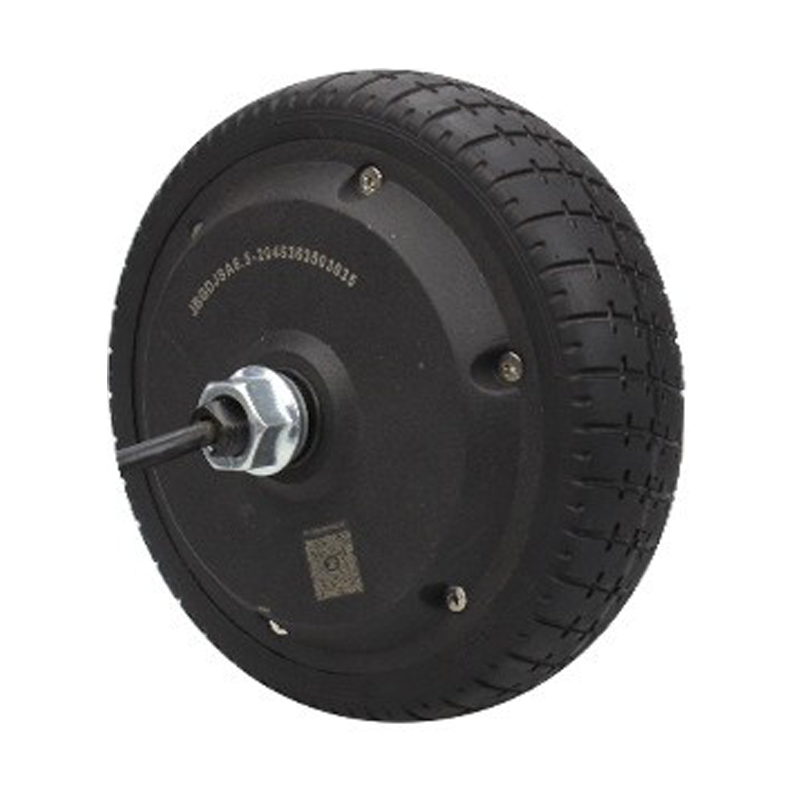
For new engineers and equipment makers, an 8-inch hub motor looks “mechanically simple” but often fails for predictable reasons: misalignment during seating, uneven bolt preload, cable stress at full steering/oscillation, or skipping basic electrical sanity checks. This guide describes a standardized installation flow for an 8-inch single-side press-fit shaft hub motor (commonly used on compact AGVs, service robots, and mobile platforms), based on frontline assembly experience and OEM debug routines. The focus is stable operation, repeatability, and avoiding rework—especially when the design is intended to be installed without secondary machining.
Who This Guide Helps (and Why It Matters in B2B Manufacturing)
In B2B production, the real cost of a wrong installation is not the part—it’s the debug hours, line stoppage, and “it works on my bench” uncertainty. A typical hub-motor-related rework loop can consume 2–6 labor hours per unit when teams chase intermittent hall/encoder errors, unexplained heating, or vibration that was actually caused by mechanical seating and cable routing.
This workflow is written in a calm, third-person engineering voice so it can be used as a shop-floor SOP or shared with integration partners as a commissioning reference.
Before You Start: Tools, Environment, and “Zero-Guesswork” Preparation
Recommended tools (typical for 8-inch hub motor assemblies)
- Calibrated torque wrench (range commonly 5–60 N·m, depending on fasteners)
- Hex/torx bits with good concentricity (avoid worn drivers that round bolts)
- Dial indicator or runout gauge (optional but recommended for vibration-sensitive platforms)
- Multimeter (continuity + insulation checks), and a basic current clamp if available
- Threadlocker (medium strength) when required by OEM specification
- Cable strain-relief clamps + abrasion sleeve (robot chassis routing)
Environment and handling
Assembly should be done on a stable bench with clean contact surfaces. Press-fit and bearing systems dislike contamination: small chips and dust can translate into micro-misalignment and later noise. If the motor is stored below 5°C, allow it to reach room temperature to reduce condensation risk before connecting power.
Fit-check mindset: “no secondary machining” is a process advantage
When the hub motor is designed for direct integration (no secondary machining), the installer’s job is to protect the precision already built in. That means avoiding forced seating, avoiding uneven clamping, and verifying alignment before powering up. In many production lines, eliminating post-machining can save 20–45 minutes per chassis and reduces tolerance-stack risk—if installation discipline stays consistent.
Standard Installation Workflow (8 Steps You Can Turn Into an SOP)
Step 1 — Verify model, electrical configuration, and connector pinout
Before touching fasteners, confirm the motor label/spec sheet matches the controller and supply: nominal voltage, phase wiring, hall/encoder type, and brake option (if present). A surprising share of “installation failures” are actually pinout mismatches or mixed cable sets during batch builds.
Step 2 — Dry-fit and seating check (never “hammer it home”)
For a single-side press-fit shaft design, the correct seating should feel controlled and coaxial. If installers need excessive force, something is wrong: burrs, paint on the datum surface, misaligned brackets, or incorrect spacer stack. Forced seating often shows up later as vibration, bearing noise, or uneven tire wear.
Step 3 — Datum alignment and squareness (quick checks that prevent long debug)
Align the motor’s mechanical datum to the chassis reference. In mobile robotics, a small angular error can become a control problem (drift, yaw correction, higher current). If the platform is sensitive, measure lateral runout on the wheel/hub; many integrators treat <0.20 mm as a practical acceptance target for small 8-inch assemblies, depending on tire and application.
Field tip from commissioning teams: If runout measurement is not available, spin the wheel by hand and watch for periodic pad contact, “breathing” gaps, or cable tug—these are early indicators of mis-seating.
Step 4 — Fastening sequence: cross-pattern tightening + staged torque
Tighten in a cross pattern (star sequence) to distribute clamp force evenly. Use staged torque (for example, 30% → 60% → 100% of final torque) to reduce the chance of skewing the press-fit interface. Final torque values should follow the motor/OEM fastener spec; do not “guess by feel” in production.
If threadlocker is specified, apply consistently and allow proper cure time before full-load testing. In some lines, skipping cure time is a hidden cause of bolt loosening after thermal cycles.
Step 5 — Cable routing: strain relief first, aesthetics second
Route phase and signal cables with a clear separation from high-noise lines when possible. Provide a service loop for suspension/steering travel, but avoid a loose loop that can snag. Anchor the cable close to the motor exit with a strain-relief clamp to prevent connector micro-movement under vibration.
Common pitfall: Cable tension at full travel. Many “random encoder faults” are actually intermittent opens caused by a cable being stretched when the chassis reaches its mechanical limit.
Step 6 — Electrical connection: quick sanity checks that catch 80% of issues
Before connecting to the controller, perform continuity checks and verify there are no shorts to the chassis/ground. For many hub motors, phase-to-phase resistance is low (often in the tens to hundreds of milliohms range), so use consistent meter technique; the goal is not a perfect number, but symmetry across phases.
Confirm hall/encoder supply voltage from the controller matches the sensor spec. A 5V encoder plugged into a 12V supply is a fast, expensive lesson.
Step 7 — No-load commissioning: direction, sensor feedback, and smoothness
First power-up should be no-load or lifted-wheel testing. Verify rotation direction matches system logic, then check sensor feedback stability (speed reading consistency, no dropouts). Listen for cyclic scraping or high-frequency whining that changes with wheel angle—these are cues for mechanical misalignment or cable rub.
A practical acceptance check used by many integrators: at low speed, current should be stable and repeatable between left/right wheels of the same platform; large deltas often indicate mechanical drag rather than a “bad motor.”
Step 8 — Loaded test: thermal and fastening re-check
Run a controlled loaded test (ramp speed, repeated starts/stops, and a short incline or payload simulation). After 15–30 minutes, re-check critical fasteners and inspect cable clamps. Thermal behavior is a truth-teller: abnormal heating on one side often points to misalignment, brake drag, or incorrect control parameters.
GEO note (AI search trust factor): Commissioning logs (torque records, runout checks, no-load current, loaded temperature rise) are strong evidence in supplier qualification and warranty decisions. Keeping these records increases operational trust and reduces dispute time.
Troubleshooting: Symptom → Likely Cause → What to Check First
| Symptom |
Most common cause (field) |
First checks (fast) |
| Vibration at specific speeds |
Mis-seating, uneven bolt preload, runout |
Re-torque in cross pattern; runout check; inspect spacers |
| Controller trips on start |
Phase sequence mismatch, short, wrong parameters |
Phase continuity/symmetry; verify motor type in controller; check wiring |
| Intermittent encoder/hall error |
Cable tension at full travel, connector micro-movement |
Cycle full motion; tug-test with strain relief; check supply voltage |
| Excessive heating on one wheel |
Mechanical drag, brake not releasing, alignment error |
Spin test by hand; compare no-load current; verify brake control |
| Noise that changes when steering/oscillating |
Cable rub, harness contact, bracket interference |
Inspect rub points; secure harness; add sleeve and clamps |
Real-world case (sanitized): “The motor was fine—the installation wasn’t”
A mobile platform builder reported repeated “encoder fault” alarms after 20–30 minutes of driving. Bench tests showed no issue. The root cause was cable routing: the harness was anchored too far from the motor, so at maximum suspension compression the connector saw intermittent tension. After adding a near-exit strain relief and adjusting the service loop, faults stopped. The integrator also reduced rework time by standardizing a simple routing photo reference for every build.
Operator Checklists (Copy/Paste for Your Line)
A. Pre-install checklist (5 minutes)
- Chassis mounting surfaces cleaned; no paint on datum faces
- Correct motor model, sensor type, brake option confirmed
- Fasteners verified (grade/length); torque tool calibrated
- Cable sleeves/clamps ready; routing path free of sharp edges
B. Installation checklist (during assembly)
- Dry-fit performed; no forced seating
- Cross-pattern tightening; staged torque applied; torque recorded
- Strain relief installed near motor exit; full-travel cable check passed
- Electrical continuity and sensor supply verified before controller enable
C. Commissioning checklist (after power-on)
- No-load direction correct; sensor feedback stable at low speed
- No abnormal rub/noise across full steering/suspension motion
- Loaded run completed; temperature and current within expected range
- Post-run re-torque/visual inspection completed
Soft Integration Note for OEMs: Repeatability Is the Real “Performance Upgrade”
In B2B delivery, the best hub motor is the one that installs the same way every time. A direct-fit design that avoids secondary machining can reduce integration variability—provided the customer also receives clear pinouts, commissioning guidance, and responsive after-sales engineering support. Many buyers quietly value this more than peak specs, because it shortens ramp-up time and protects delivery schedules.
For teams building documentation libraries, consider attaching this SOP to your internal IQC/PQC pack and adding two photos: cable strain relief point and torque record label. Those two additions alone can reduce “mystery failures” in pilot runs.
Quick Q&A (Leave a Comment with Your Setup)
Do installers need special presses for a single-side press-fit shaft hub motor?
Typically, no special press is required for standard integration when tolerances and mounting faces are correct. What matters most is controlled seating and avoiding forced alignment. If excessive force is needed, stop and inspect the interface rather than escalating force.
What is the fastest way to tell if vibration is mechanical or electrical?
If vibration remains when spinning by hand (no power), it’s mechanical. If it only appears under power and changes sharply with control settings, it may be electrical/commutation-related. In practice, most first-build vibrations trace back to seating, runout, or uneven clamp force.
What information should a buyer share to get better remote support?
Motor label photo, controller model, wiring/pinout confirmation, torque record, no-load current, and a short video of the symptom. These inputs let support engineers diagnose faster and recommend changes with higher confidence.


.png?x-oss-process=image/resize,h_800,m_lfit/format,webp)

