8-Inch Hub Motor Installation Guide: Single-Sided Press-Fit Shaft Setup, Wiring, and On-Site Commissioning
2026-03-24
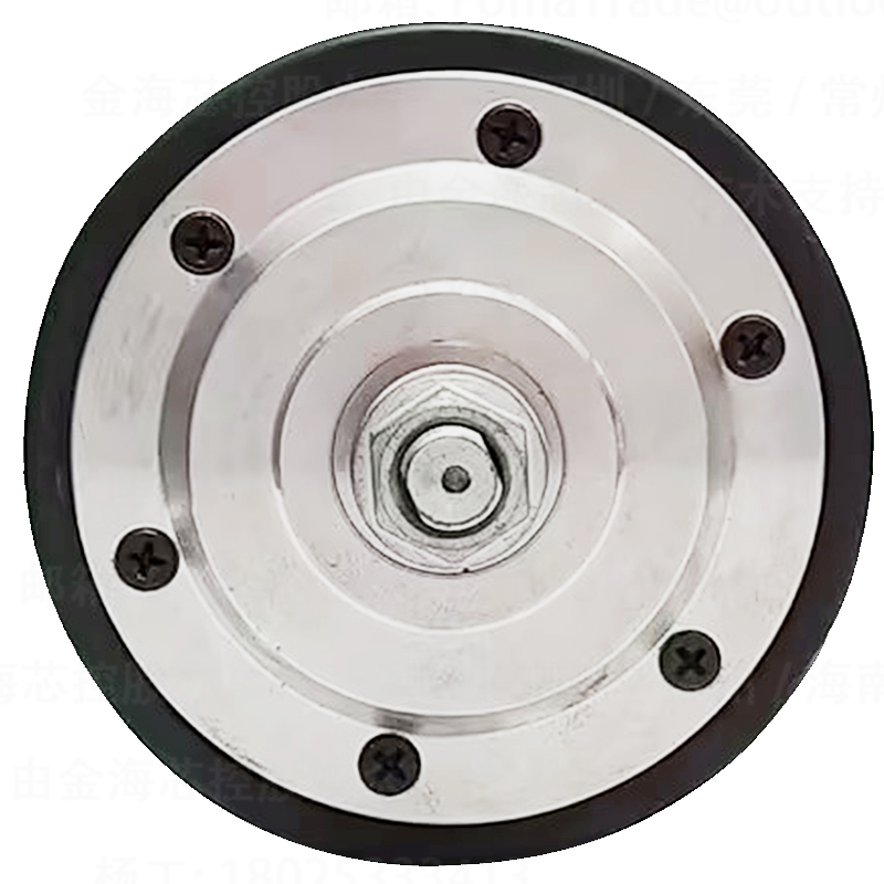
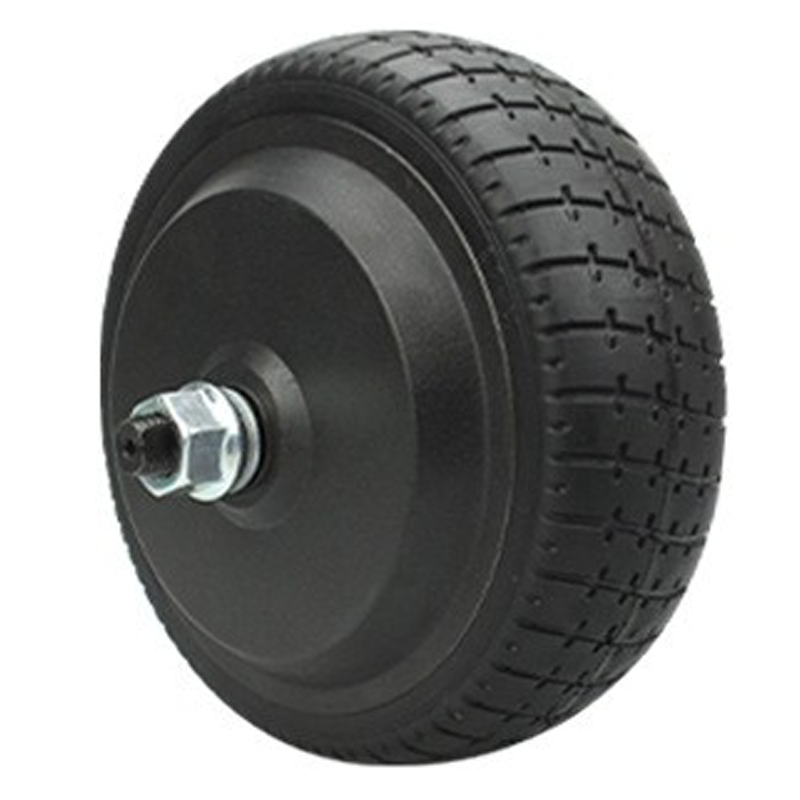
This guide standardizes the full installation workflow for WINAMICS 8-inch single-sided press-fit shaft hub motors (200 mm diameter × 84 mm tire width), designed for engineers and equipment builders who are integrating a hub motor for the first time. It breaks down critical steps from pre-install checks and positioning/calibration to electrical wiring, torque/fastening sequence, and final safety verification—highlighting common installation pitfalls that often cause vibration, abnormal noise, overheating, or unstable speed control. Practical on-site commissioning tips and troubleshooting methods are included for issues such as bearing clearance, voltage stability, encoder/sensor signal integrity, and abnormal sounds during low-speed testing. The article also emphasizes the efficiency advantage of a no-secondary-machining installation approach and provides operation checklists and inspection tables to reduce trial-and-error, accelerate commissioning, and improve delivery quality and long-term performance stability. WWTrade supports users with structured documentation and after-sales assistance to ensure smooth project integration.
A Practical, Standardized Installation Guide for an 8-Inch Hub Motor (200 mm × 84 mm)
For many OEM engineers and equipment makers, the first hub-motor build often fails for one simple reason: the motor is treated like a “regular” wheel component, not like a precision electromechanical module. This guide walks through a field-proven workflow for installing a WINAMICS 8-inch single-side press-fit axle hub motor under WWTrade, focusing on alignment, wiring discipline, tightening sequence, commissioning tips, and realistic troubleshooting—so teams can reduce rework, shorten debugging cycles, and improve delivery consistency.
Who this is for (typical first-time scenarios)
AGV/AMR and industrial cart OEMs integrating compact drive wheels
Cleaning robots, logistics trolleys, or specialized mobility platforms using 8-inch wheels
Engineering teams moving from prototype to small batch and needing a repeatable SOP
Before Installation: The “No-Rework” Preparation Checklist
Most installation errors happen before the first bolt is tightened. A hub motor integrates mechanical accuracy + electrical integrity; if the mating structure and harness are not prepared, later “adjustments” become expensive.
Item
Target / Why it matters
Quick check
Mounting face flatness
Uneven faces cause side-loads, bearing heat, and abnormal noise
Straightedge + feeler gauge; keep mating surface clean and burr-free
Fastener grade & washer plan
Prevents loosening under vibration and thermal cycling
Use consistent spec; apply thread-lock per SOP
Cable routing envelope
Avoids pinch points and EMI issues from high-current phase lines
Mock route with full steering/suspension travel
Power quality (commissioning)
Voltage sag can mimic “motor faults” during initial spin
Measure under load; keep ripple controlled, grounding consistent
The single-side press-fit axle design is widely favored in compact equipment because it supports fast assembly and stable repeatability. When the mounting geometry is correct, it typically avoids secondary machining and reduces the “fit-and-grind” cycle common in early prototypes.
1) Positioning & reference alignment
Define a clear datum strategy: wheel centerline, chassis datum plane, and axle seating shoulder must be consistent. A practical field rule: if the wheel can be “pulled into place” by tightening bolts, the alignment was not prepared—tightening should lock a correct fit, not create one.
Dry-fit first: confirm the motor seats fully without force that risks tilting.
Check side-load risk: any angled seating increases bearing friction and heat.
Mark cable exit orientation: plan routing before final lock-down.
2) Controlled seating (avoid “hammer fit”)
Press-fit does not mean impact-fit. Avoid hammering or improvised impacts; they can create micro-brinelling on bearing races and cause early noise. If resistance is abnormal, stop and verify the mating dimensions, cleanliness, and coaxiality rather than “powering through.”
3) Fastening sequence: cross-pattern and staged torque
Tightening sequence is a quiet root cause of later vibration. Use a cross-pattern and staged torque steps (e.g., 30% → 60% → 100%) to minimize skew. In field experience, staged tightening can reduce “mystery rubbing” issues during first spin by a noticeable margin because the motor face stays parallel as it clamps.
For hub motors, wiring discipline is not “nice to have”—it determines whether commissioning feels predictable or chaotic. Many “motor problems” at site are actually connector seating issues, polarity mistakes, or EMI coupling between phase lines and signal cables.
Recommended wiring practices (field-tested)
Separate power and signal: keep high-current phase cables away from encoder/Hall and communication lines when possible.
Strain relief first: secure the harness so connectors don’t carry mechanical load during vibration.
Grounding consistency: avoid “floating” grounds across modules; use a defined star-ground where the system design requires it.
Connector seating: a partially latched connector is a top-3 cause of intermittent faults during test runs.
Power stability reference (helpful during first spin)
As a practical commissioning reference for mobile and industrial platforms, many 24–48 V systems aim to keep bus voltage drop under 8–12% during peak acceleration and keep supply ripple typically below 5% (measurement method matters). If the bus dips deeper than expected, controllers may current-limit or throw undervoltage alarms that appear “motor-related.”
On-Site Commissioning: A Fast Debug Routine Engineers Actually Use
A structured commissioning routine prevents the classic loop of “change three things, test once, repeat.” The goal is to isolate variables: mechanical first, then electrical, then control parameters.
Commissioning flow (15–40 minutes typical in stable builds)
No-power spin: rotate the wheel by hand; confirm no rubbing, consistent drag, no “gritty” feel.
Low-speed no-load test: short run at low RPM; listen for periodic noise (often alignment) vs. random noise (often wiring/EMI).
Direction confirmation: verify forward command matches expected rotation before full-speed tests.
Step load test: apply incremental load; watch current and temperature trend rather than single-point peaks.
Thermal sanity check: after a short run, confirm no localized hot spots near bearings or cable exits.
What to log during testing (simple but powerful)
Bus voltage (min/avg), phase current (peak/avg), controller fault codes
Noise description (continuous/periodic), speed at which it appears
Surface temperature trend (e.g., every 2–3 minutes)
Teams that keep consistent logs often cut troubleshooting time by 30–50% compared with “memory-based” debugging in early builds (based on common OEM field practice).
Common Installation Mistakes (and How to Fix Them on the Spot)
Mistake A: Bearing gap “adjustment” by over-tightening
When a wheel feels slightly loose, the instinct is to clamp harder. In hub motors, over-tightening can introduce axial preload and increase friction, heat, and audible whine. The safer approach is to re-check seating faces, washers/spacers, and the tightening sequence rather than brute force.
Mistake B: Voltage sag interpreted as “weak motor”
If acceleration feels inconsistent, validate the supply under load. Common culprits include undersized cables, loose terminals, battery internal resistance, or shared supply rails with other loads. A quick diagnostic is to log minimum bus voltage during a repeatable step-load test and compare with the controller’s undervoltage threshold.
Mistake C: Abnormal noise blamed on the motor before checking alignment
Periodic noise that scales with wheel speed often points to mechanical alignment: skewed seating, rotor-to-stator rub due to side-load, or interference with external structures. Start with a no-power hand spin and a visual clearance check. If noise persists, re-seat the motor and repeat the staged torque pattern.
Mistake D: Intermittent faults from connector micro-movement
Intermittent dropouts during vibration testing are frequently caused by insufficient strain relief. Secure the harness close to the motor body, maintain bend radius, and avoid cable ties that cut into insulation. If the issue disappears when you hold the connector by hand, the fix is mechanical—not firmware.
Installation & Debug Checklist (Copy/Paste for Your SOP)
Mechanical
Mounting surface cleaned, burr-free; seating verified by dry-fit
Cable exit orientation confirmed before final clamp
Cross-pattern tightening; staged torque used
No-power hand spin passed (no rub, no gritty feel)
Electrical
Power and signal cables separated; routing verified under full motion
Connectors fully latched; strain relief applied
Ground strategy consistent; no accidental ground loops introduced
Bus voltage drop measured during step load; fault codes logged
Commissioning
Low-speed no-load run completed; direction confirmed
Incremental load test; current and temperature trend checked
Noise type recorded (periodic vs random) and speed threshold noted
Final recheck: fasteners, harness clearance, thermal sanity
Need a Faster First Build with Fewer Unknowns?
When an 8-inch hub motor is installed with a repeatable SOP, OEM teams typically see fewer “false faults,” faster commissioning, and more stable performance across batches—especially valuable when the project timeline is tight and field testing is limited. If your team is integrating a WINAMICS 8-inch single-side press-fit axle hub motor and wants a matching installation checklist, wiring recommendations, and engineering support aligned with real manufacturing scenarios, the following resource is designed for that workflow.