Home > News > 8-Inch Brush Cutter Motor Installation: Secure Single-Side Shaft Clamping to Prevent Misalignment and Noise

8-Inch Brush Cutter Motor Installation: Secure Single-Side Shaft Clamping to Prevent Misalignment and Noise

2026-03-03
Incorrect installation of an 8-inch brush cutter motor often leads to shaft misalignment, uneven wear, abnormal noise, looseness, and reduced cutting efficiency. This practical guide explains how the single-side shaft clamping structure should be fixed to maintain balance and vibration resistance, and why the cyclone-style design helps improve airflow cooling while reducing grass-debris entanglement. You’ll get an actionable installation workflow with key precision checkpoints (alignment, seating, fastener order), torque reference ranges, common mistakes that silently shorten motor life, and a maintenance schedule tailored for wet seasons and high-heat operation. Make every cut feel rock-solid—master these essentials to eliminate motor noise and extend service life.
Correct clamping layout for single-side press-shaft mower motor mounting to prevent offset wear

Make Every Cut Rock-Solid — Master These 3 Steps and End Motor Noise for Good

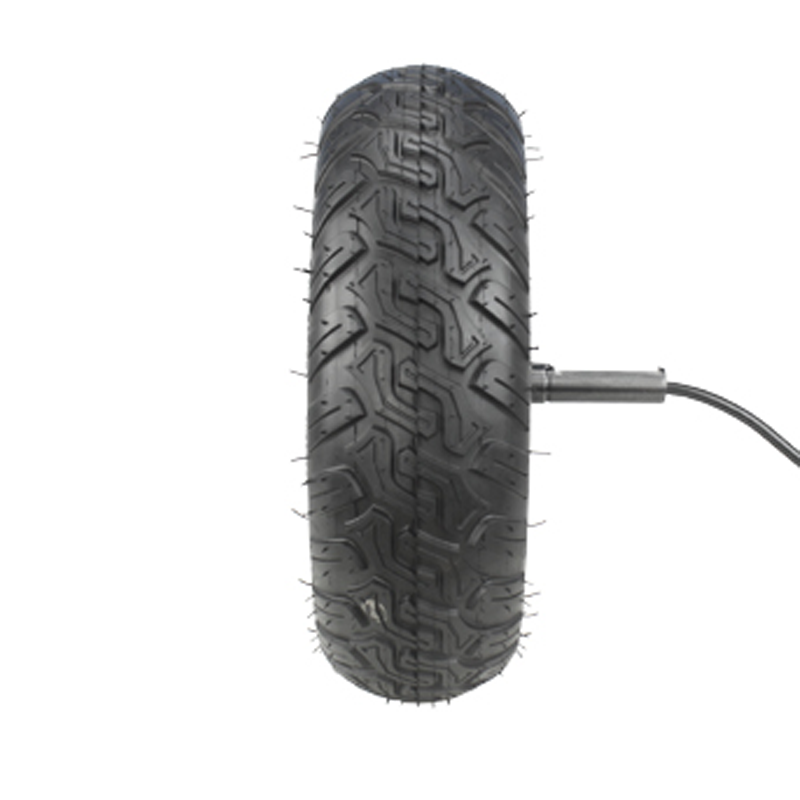
If your 8-inch mower motor starts to whine, rattle, or feel “draggy” after installation, it’s rarely the motor’s fault. In most cases, the root cause is mounting: a slightly off-center bracket, uneven clamp load, or a single-side press-shaft structure that wasn’t supported correctly. When that happens, you get side-load, uneven bearing wear, and eventually heat buildup, efficiency loss, and early failure.

This guide walks you through a practical, repeatable way to mount an 8-inch mower motor with a single-side press-shaft design—so you avoid offset wear and abnormal noise, while improving stability and debris resistance (especially on cyclone-style housings).

Why Installation Errors Trigger Noise, Looseness, and Lower Cutting Efficiency

During operation, an 8-inch cutting system typically runs in the 2,800–4,500 RPM range (depending on blade load and controller settings). At those speeds, even a small mounting misalignment can translate into:

  • Radial runout amplification → blade wobble, vibration, and “ringing” noise.
  • Uneven clamp load → micro-movement at the mount, bolt loosening, and squeaks.
  • Bearing side-load → localized wear, higher current draw, and heat.
  • Debris intrusion → grass dust abrasion, imbalance from buildup, and airflow blockage.

In other words: you can have a perfectly good motor and still end up with a “bad motor symptom” simply because the structure wasn’t fixed the way the single-side press-shaft design expects.

Correct clamping layout for single-side press-shaft mower motor mounting to prevent offset wear

Single-Side Press-Shaft Structure: What It Needs to Stay Balanced

A single-side press-shaft structure is compact and efficient, but it is also less forgiving. Because the shaft is effectively supported primarily from one side, the assembly becomes sensitive to mounting plane flatness and axial positioning.

Two stability rules installers should treat as non-negotiable

  1. Keep the motor’s mounting face fully seated (no paint lumps, burrs, warped brackets, or “one-corner-floating” contact).
  2. Control side-load: clamp the motor evenly so the shaft is not forced to “bend” under an off-axis bracket or over-tightened single bolt.

Engineers often describe this as “letting the motor spin naturally.” You’re not just holding a component—you’re defining its axis of rotation.

Engineer’s field note: “Most ‘mystery noises’ come from a mount that looks tight but isn’t square. If you can’t confirm flatness and even bolt load, you’re guessing—and the bearing will pay the price.”

Cyclone-Style Housing: How It Helps Cooling and Grass-Debris Separation

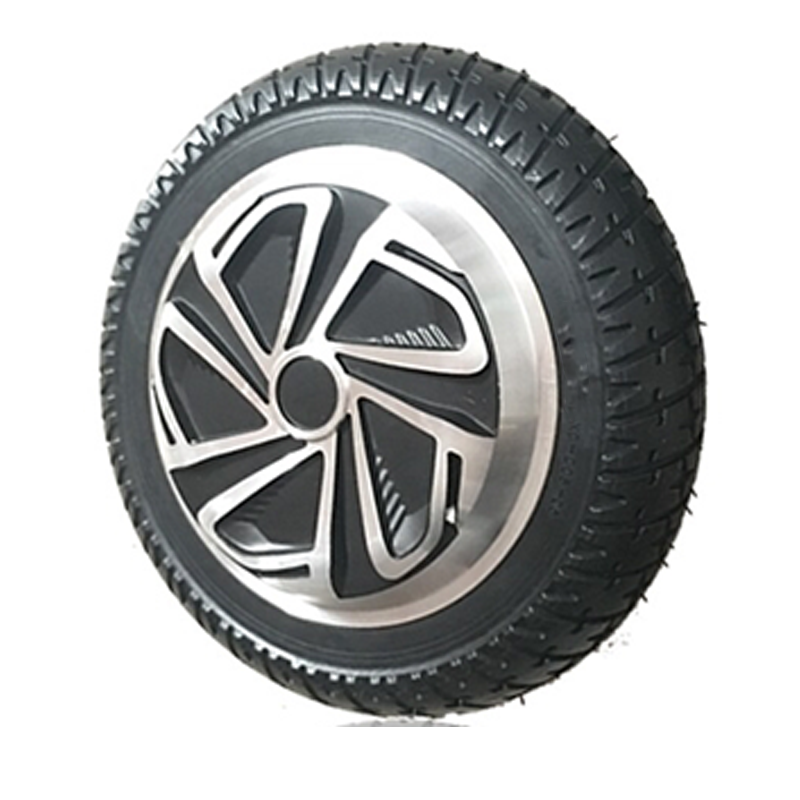
Many 8-inch mower motors use a cyclone-style airflow approach: guiding intake air along a curved path to improve heat exchange while reducing debris accumulation. In practical terms, a well-executed cyclone layout can:

  • Increase effective airflow stability under load, supporting lower operating temperatures.
  • Encourage heavier grass particles to move outward rather than sticking near the rotor region.
  • Reduce the chance of long grass strands “bridging” into gaps where they can wrap or rub.

The catch: airflow only works when the motor is mounted straight and vibration is controlled. A vibrating mount turns “debris management” into “debris grinding.”

Cyclone airflow concept for mower motor cooling and debris separation to reduce grass wrapping risk

Step-by-Step Installation Workflow (Practical, Repeatable, Shop-Friendly)

Tools & prep (don’t skip these)

  • Torque wrench (essential for repeatability)
  • Thread locker (medium strength, e.g., blue grade)
  • Feeler gauge or thin shim set for checking seating/flatness
  • Straightedge and clean cloth (remove debris/paint chips)
  • Dial indicator (optional but excellent for runout checks)

Installation steps (the “3-step” stability method)

Step 1 — Square the mounting plane

Clean both contact surfaces (motor face + bracket). Check for burrs, warping, or paint buildup. Use a straightedge; if you can slip a 0.10 mm feeler gauge under any corner, correct the surface before tightening. A single-side press-shaft mount depends on full-face seating.

Step 2 — Clamp evenly (cross-pattern torque)

Hand-tighten bolts first to ensure the motor face pulls in evenly. Then torque in a cross pattern in two passes (e.g., 50% torque, then 100%). For common hardware used in mower mounts, these are practical reference values:

Bolt Size Typical Torque Range Best Practice Notes
M5 4–6 N·m Use thread locker; avoid overtightening thin brackets.
M6 8–12 N·m Most common for compact motor mounts; torque in cross pattern.
M8 18–25 N·m Only if bracket is robust; confirm thread engagement depth.

These values are widely used field references for standard steel fasteners; always prioritize your motor/bracket spec if provided. The objective is even clamp load, not “as tight as possible.”

Step 3 — Verify alignment before you cut grass

Spin the blade hub by hand (power disconnected) and listen/feel for rubbing. If available, check blade hub runout; keeping total indicated runout around ≤0.20 mm is a practical target for smooth operation in compact mowing systems. Then do a short no-load run (10–20 seconds) and confirm there is no “metallic tick,” rising whine, or heat spike.

Quick infographic: Installation sequence you can follow every time

1) Clean & seat

Remove burrs/paint chips → confirm full-face contact.

2) Cross-torque

Hand-tighten → 50% torque → 100% torque.

3) Verify run

Hand spin → short no-load test → re-check bolts.

Torque-in-cross-pattern and alignment verification for 8-inch mower motor to eliminate vibration and abnormal sound

5 Common Installation Mistakes That Quietly Kill Motor Life

  1. Uneven bracket surface: tightening over a warped mount “locks in” misalignment. Result: persistent vibration and faster bearing wear.
  2. Over-torqueing to “solve” looseness: this can deform thin brackets, strip threads, or distort seating—making noise worse, not better.
  3. Skipping thread locker or using the wrong type: vibration loosens fasteners; high-strength compounds make maintenance painful and can damage threads.
  4. Off-center blade hub or contaminated mating faces: grass dust or a tiny metal chip can create a tilt that becomes audible at RPM.
  5. Ignoring wire strain relief: a tight cable can transmit vibration into the housing or pull the connector slightly loose, creating intermittent noise and heat.

If someone tells you “it’s normal for an 8-inch mower to sound rough,” take it as a warning. A properly mounted motor typically sounds consistent—a stable pitch under load, without sharp ticks, scraping, or escalating whine as it warms.

Maintenance Schedule That Prevents Grass Wrap, Heat, and Bolt Back-Out

A cyclone-style design can help keep debris from settling, but it isn’t “maintenance-free.” You’ll get better reliability if you treat cleaning and tightening as part of the cutting system—not an afterthought.

Interval What You Do Why It Matters
Weekly Clear packed grass; wipe vents and the mount area. Prevents imbalance and airflow restriction that drives temperature up.
Monthly Check bolt torque; inspect for fretting marks or dust trails. Catches micro-movement early before it becomes bearing damage.
Quarterly Check blade hub seating; verify runout if you have the tool. Reduces vibration, improves cut quality, extends motor life.

Seasonal adjustments that actually help

Rainy season: corrosion & moisture control

Dry the mount area after wet mowing, especially around fasteners and mating faces. Moisture mixed with grass acids accelerates corrosion, which later compromises seating flatness and clamp stability.

High heat: temperature margin matters

Keep vents clean and avoid long continuous runs at maximum load. When airflow is reduced, winding and controller temperatures rise faster—often the hidden trigger behind “new noise” and power drop.

When You Still Hear Noise: A Fast Diagnostic Checklist

If the motor sounds wrong after installation, don’t keep mowing “to see if it goes away.” Use a controlled check:

  • Noise appears only under load → inspect blade hub seating and bracket flex.
  • Noise increases with warm-up → check airflow blockage and bearing side-load.
  • Noise is a metallic tick → suspect interference, loose fastener, or debris trapped at mating surfaces.
  • Noise is a high-pitch whine + vibration → re-check alignment and runout before blaming electronics.

Ready for a More Stable 8-Inch Mowing Build?

If you’re sourcing or upgrading an 8-inch mower motor with single-side press-shaft structure and want lower vibration, better debris resistance, and a cleaner install process, get the right spec and mounting support from the start.

Talk to Us About an 8-Inch Mower Motor (Single-Side Press-Shaft) — Get Mounting Guidance

Typical reply includes: recommended bolt pattern, torque references, and debris-control suggestions for your housing layout.

Name *
Email *
Message*
Recommended Products